Reznor RPBL Unit Installation Manual User Manual
Page 35
Form I-SSCBL/RPBL, P/N 149159 R7, Page 35
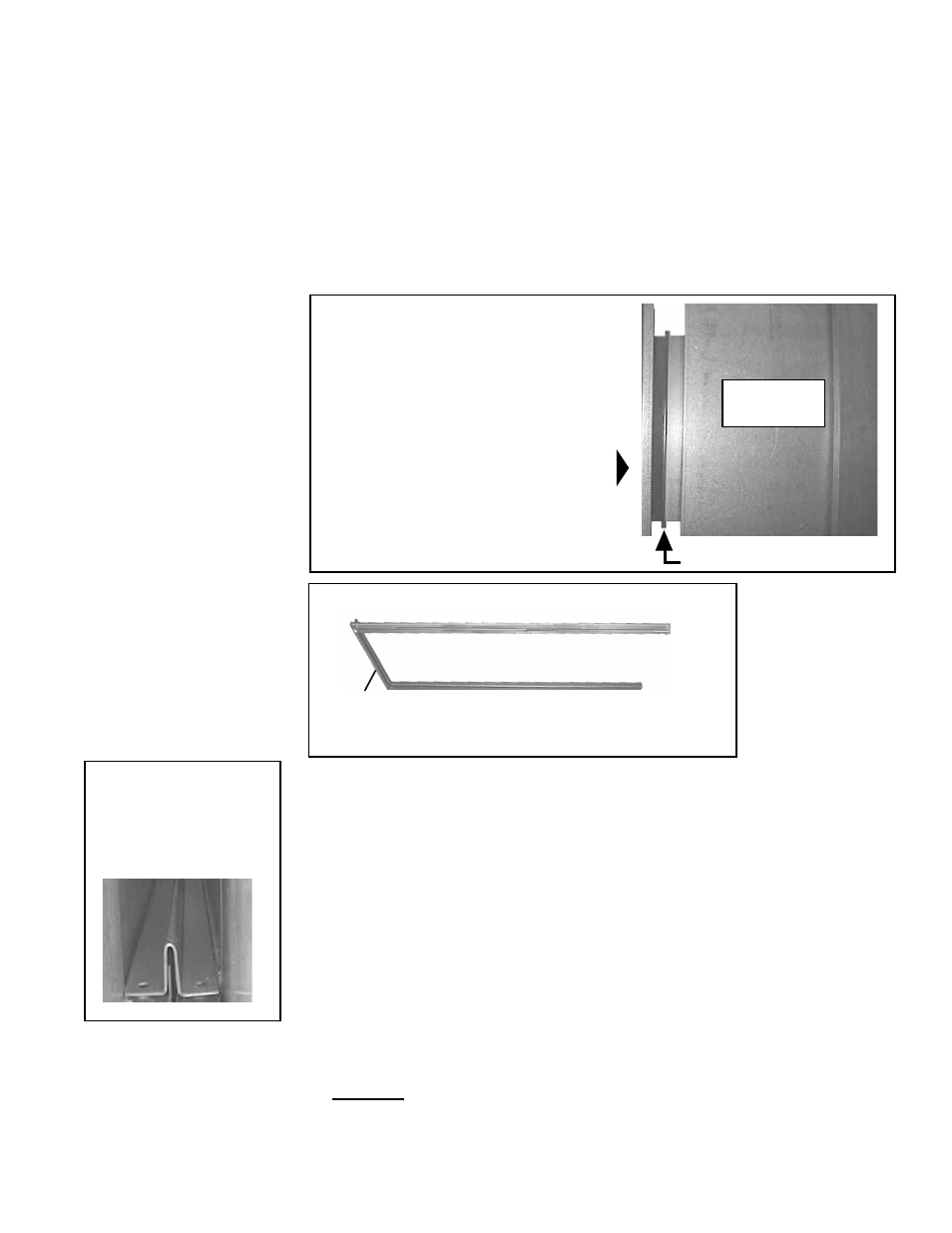
FIGURE 40C - The
end of the top
connector on the
"open side" of the
connector assembly.
FIGURE 40B - Assemble
top, bottom, and
one side of the duct
connector pieces using
the 3/4" sheetmetal
screws
b) Position the assembled connectors so that the screw holes will be in the
top piece at the open side
(See FIGURE 40C). In this position, insert the
assembled top and bottom connectors into the space between the furnace and
the cooling coil cabinet.
Tap with a hammer, first on the side, then on the top, and last on the bottom of
the assembled duct connector until it is seated over both duct flanges.
c) Position the remaining side connector. Use a driver extension to insert the
screws that attach the side connector to the top and bottom connectors.
See
FIGURE 40D.
5. Wiring Instructions - Apply to Downturn Plenum Cabinet with Optional
Discharge Dampers Only - If installing an Option AU12 or AU14 cooling coil
cabinet with a downturn plenum cabinet equipped with optional discharge
dampers, the damper motor wires must be connected to the terminal blocks in the
furnace electrical compartment. If the coil cabinet being installed does not include
a downturn plenum with a discharge damper, skip Step 5 and proceed to Step 6.
a) Drill three 7/8" holes as instructed below. Be sure all holes are free of burrs.
First Hole:
1) Remove the control side door on the discharge plenum.
2) Locate the discharge damper motor. Connected to the motor are three wires in
lengths adequate to reach the furnace section.
Top of Assembled Duct Flange Connectors
Bottom of Assembled Duct
Flange Connectors
Assemble with
only one side
piece
FIGURE 40A -
1) Place the cooling coil
cabinet on the curb;
2) Remove the lifting lugs;
and
3) Slide the cabinet so
that the duct flange on
the cooling coil cabinet
butts against the duct
flange on the furnace.
Furnace
Discharge
with Duct
Flange
Duct Flanges
Airflow
Cooling Coil
Cabinet
Instructions for Lifting
and Attaching Cabinet
(NOTE: If suspending
cabinet, consult factory.)
1. After the blower/furnace packaged system is in place on the roof curb or mounting
rails, use a 9/16" wrench or socket to remove the lifting lugs that are on the
discharge end of the system.
2. Lift the cooling coil cabinet and position it with the inlet side next to the discharge
opening of the furnace. Remove the lifting lugs that are on the cooling coil cabinet.
3. Slide the cooling coil cabinet so that the duct flanges of the furnace and the
cooling coil cabinet butt together
(See FIGURE 40A).
4. Join the Duct Flanges
a) Use the four "U" shaped duct connector pieces and the 3/4" screws to join the
duct flanges. Attach one of the 19-1/2" (495mm) long side connectors to both
the top and bottom duct connectors, being sure that the "U" in the metal is open
to the inside.
(See FIGURE 40B.)