0 controls (cont'd), 8 gas controls (cont'd) – Reznor RPBL Unit Installation Manual User Manual
Page 48
Form I-SSCBL/RPBL, Page 48
Size
Maximum
Turndown
MBH Input
Range
Inlet Pressure to Modu-
lating Valve (factory set)
Gas Supply
Pressure Required
400
25%
100-400
4.4" w.c.
6" w.c.
500
28%
69-250
4.0" w.c.
5" w.c.
600
23%
69-300
4.0" w.c.
5" w.c.
800
25%
100-400
4.4" w.c.
6" w.c.
1200
25%
100-400
4.4" w.c.
6" w.c.
Carryover
Regulator
P rimary Gas
Flow Pressure
Switch
White Label
1.1 w.c.
Gas Flow
Pressure Switch
White Label
1.1 w.c.
Modulating
Valve
Single-Stage
Gas Valve
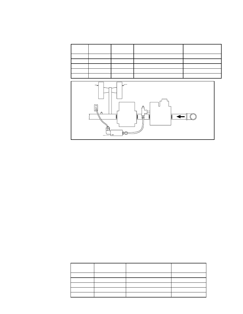
FIGURE 51 - Manifold
Arrangement on
Furnace with Optional
Electronic Modulation
between 25-100% Firing
Rate
Note: Arrangement may vary slightly depending
on gas valve; components are the same.
The gas train (
FIGURE 51) in a furnace with this type of electronic modulation control
includes a single-stage gas valve, a modulating valve, and two gas pressure switches.
The burner rack is equipped with one flash carryover and a regulated gas lighter tube
system. The carryover lighter tube receives its gas supply through the regulator, simul-
taneously with the gas to the burner. Control of the system is through a Maxitrol ampli-
fier with a corresponding remote temperature dial.
Description of
Operation - furnace
with Option AG39,
AG40, AG41 or AG42
Combustion Air
Pressure Switch
Setting
This uniquely designed modulation system requires combustion air pressure settings
different from the standard system. The approximate settings for the combustion air
proving switch at sea-level operation are shown in the table.
w/AG 39,
40, 41, 42
Startup Cold
Equilibrium at Full
Rate
Factory Setting
400
-1.2"w.c.±0.2
-0.95"w.c.±0.1
-.75"w.c.±0.5
500
-1.2"w.c.±0.2
-0.95"w.c.±0.1
-.75"w.c.±0.5
600
-1.2"w.c.±0.2
-0.95"w.c.±0.1
-.75"w.c.±0.5
800
-1.2"w.c.±0.2
-0.95"w.c.±0.1
-.75"w.c.±0.5
1200
-1.2"w.c.±0.2
-0.95"w.c.±0.1
-.75"w.c.±0.5
8.0 Controls
(cont'd)
8.8 Gas Controls
(cont'd)
8.8.4 Optional
Electronic Modulation
(cont'd)
Electronic Modulation between 25% and 100% Firing Rate), Options
AG39, AG40, AG41, AG42 (cont'd)
The furnace with this type of electronic modulation will ignite at any input rate in the
available range and will maintain average thermal efficiencies equal to or greater than
the thermal efficiency at full fire. The following table applies to the furnace with the
manifold illustrated in
FIGURE 51.
The gas supply (6" w.c. required) connects to the single-stage gas valve. To compen-
sate for additional pressure loss through the modulating valve, the single-stage gas
valve has a custom outlet pressure setting higher than when it is used on a standard
gas manifold. The pilot tubing connects to the pilot port on the single-stage gas valve.
When the valve receives a call for heat from the amplifier and pilot is established, gas
flow from the single-stage valve goes to both the modulating valve and the regulated
lighter tube system.
When the signal from the amplifier to the modulating valve
requires less-than-high fire operation, the modulating valve functions to lessen the
gas flow to the burner to reduce the input rate to that required to maintain the desired
temperature. When the input rate is reduced enough to decrease the gas pressure to
1.1" w.c., the primary gas pressure switch in the manifold activates the gear motor that
controls the bypass damper in the venter/combustion air system. The bypass damper
opens diverting some of the incoming air directly into the flue duct, reducing airflow
through the burner. Safety switches monitor the position of the bypass damper. When
the gas pressure increases above 1.1" w.c., the bypass damper closes.