0 maintenance and service (cont'd), 2 maintenance procedures (cont'd) – Reznor RPBL Unit Installation Manual User Manual
Page 56
Form I-SSCBL/RPBL, Page 56
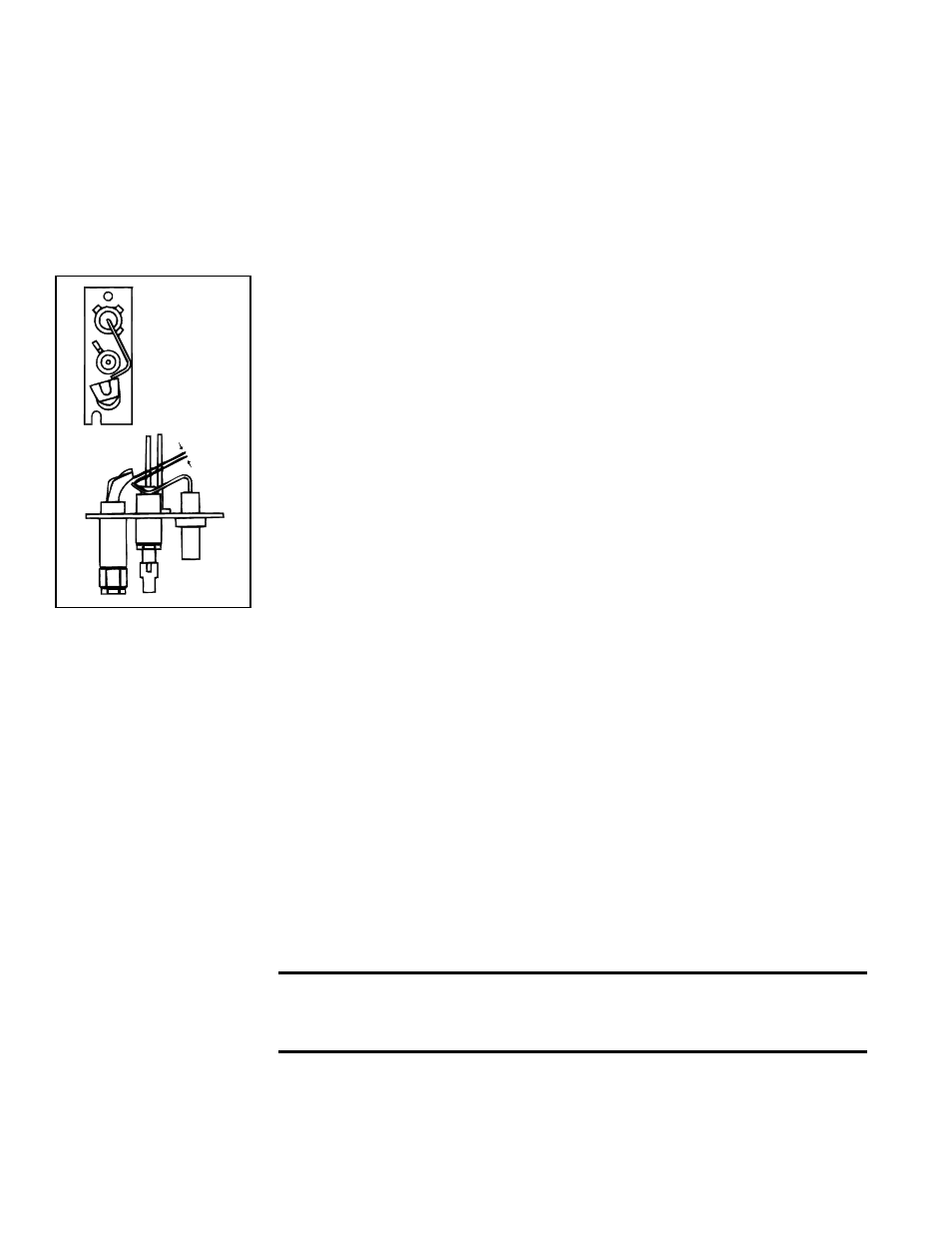
.100
Top
View
Side
View
FIGURE 58 - Pilot
Assembly Spark Gap
10.0 Maintenance
and Service
(cont'd)
10.2 Maintenance
Procedures
(cont'd)
If no spark occurs, check the following:
a) Voltage between Terminals TH and 7 on the ignition controller should be at least
20 volts and no higher than 32 volts. Refer to Troubleshooting (Paragraph 10.3) if
no voltage is observed.
b) Short to ground in the high tension lead and/or ceramic insulator.
c) Pilot spark gap should be approximately .100".
NOTE: When checking for spark with the pilot burner assembly removed from the
burner rack, the pilot assembly must be grounded to the heater for proper spark.
If the above conditions are normal and no spark occurs, replace the ignition controller.
(See controller illustration and replacement information on page 51.)
If the main gas valve fails to open with a normal full size pilot flame established, check
for the following:
a) If voltage between black and brown leads on the main gas valve is 20 to 32
VAC and there is no main gas flow with the built-in manual valve in FULL OPEN
position, the main valve is defective.
b) If there is no voltage between black and brown leads on the main gas valve, check
for disconnected or shorted flame sensor lead or flame sensor probe.
When the above conditions are normal and the main gas flow is still off, the ignition
controller is probably defective. Do not attempt to service the ignition controller; it does
not contain any replaceable components.
10.2.3 Cleaning the Heat Exchanger
To clean the inner surfaces of the heat exchanger, remove the burner rack assembly
(See Paragraph 10.2.2.) permitting access to the inside of the heat exchanger tubes.
Clean the tubes using a 1/2" diameter furnace brush. A mirror and flashlight are helpful
in examining the narrow section of each tube. Remove any accumulated dust and soot.
10.2.4 Venter Motor
Power venter motors are permanently lubricated. No oiling is required.
10.2.5 Blower, Belt, and Drive
Check blower pulley and motor pulley to be sure they are secure to the shaft. Check
belt condition and belt tension (See Paragraph 6.5).
Blower Bearings - The blower bearings on models with less than a 10 HP motor
(standard blower) are permanently lubricated cartridge ball bearings and do not require
greasing.
The blower bearings on models equipped with a 10-20 HP motor are pillow block ball
bearings and are equipped with a grease fitting. These bearings should be lubricated
twice a year with a high temperature, moisture-resistant grease. (Type NLGI-1 or -2
standard grease is recommended.) Be sure to clean the grease fitting before adding
grease.
Add grease with a handgun until a slight bead of grease forms at the seal. Be careful
not to unseat the seal by over lubricating. NOTE: If unusual environmental conditions
exist (temperatures below 32°F or above 200°F; moisture; or contaminants), more
frequent lubrication is required.
CAUTION: If the blower is unused for more than three months,
bearings with a grease fitting should be purged with new grease
prior to startup.
10.2.6 Limit Control Check
With the heater on, completely block off the distribution air. The limit control should
open within a few minutes, shutting off gas supply to the main burners.
Pilot and Spark Ignition System (cont'd)
10.2.2 Pilot and Main Burners (cont'd)