0 electrical supply and controls, 1 general, 2 supply voltage and wiring – Reznor RPBL Unit Installation Manual User Manual
Page 41
Form I-SSCBL/RPBL, P/N 149159 R7, Page 41
Optional Variable
Frequency Drive
If the system is equipped with an optional variable frequency drive, the motor will oper-
ate on speeds as determined by the electrical frequency. 60 hertz is maximum speed.
Speeds must be within the temperature rise range approved for a Model SCE Series
6 heater which is 30-90°F.
Follow the variable frequency controller manufacturer's instructions that are packaged
with the heater (in the owner's envelope) to program the variable frequency drive set-
tings. The formula for motor speed is
N = 120 x f/p where N is speed; f is frequency;
and
p is number of poles (3600 RPM motor has 2 poles; an 1800 RPM motor has 4
poles).
Example:
1800 RPM motor on 60Hz; N = 120 x 60/4 = 1800
1800 is synchronous speed; assume 2% slip. Motor will run
between 1750 and 1790 RPM at full load depending on design.
Run the same motor at 45Hz (120 x 45/4 = 1350). 1350 RPM
less 2% slip equals about 1300 RPM.
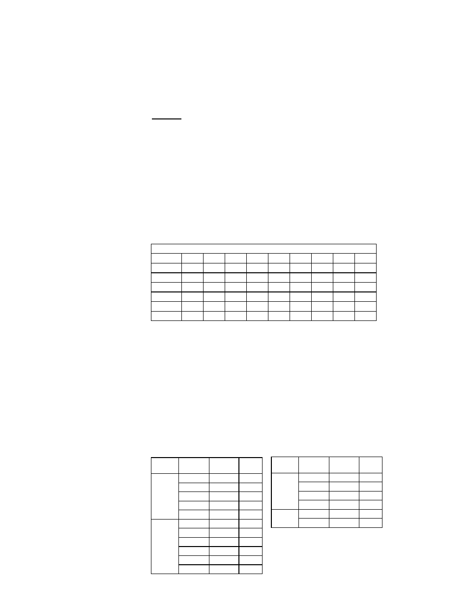
Motor Loads and Amps
Full Load Amps - Blower Motors (Open, Single Speed, Average)
HP
1
1-1/2
2
3
5
7-1/2
10
15
20
208V/1
7.2
10.1
11.3
13.7
28.0
230V/1
6.5
9.1
10.2
12.4
26.0
32.0
38.0
208V/3
3.6
5.8
7.3
9.3
14.6
23.2
28.8
42.0
55.3
230V/3
3.2
5.2
6.6
8.4
13.2
21.0
26.0
38.0
50.0
460V/3
1.6
2.6
3.3
4.2
6.6
10.5
13.0
19.0
25.0
575V/3
1.3
2.1
2.6
3.4
5.3
8.4
10.4
15.2
20.0
Use an amp meter to check blower motor amps. The following chart lists full load
amps for various HP and voltages of open-type blower motors. Amps may be adjusted
downward by reducing blower RPM or by increasing duct system static pressure. This
chart can be used for sizing line wiring but should not be interpreted as the exact motor
amps. See the motor rating plate for exact motor specifications. Do not exceed amp
rating on the motor nameplate.
Venter motor amps for a 115 volt or 575 volt unit are 1.5 amps; venter motor amps for
a 208, 230 or 460 volt unit are .8 amps.
7.0 Electrical
Supply and
Controls
7.1 General
All electrical wiring and connections including electrical grounding must be made in
accordance with the National Electric Code ANSI/NFPA No. 70 (latest edition) or, in
Canada, the Canadian Electrical Code, Part I-C.S.A. Standard C22.1. Check any local
ordinances or gas company requirements that apply.
Check the rating plate on the heater for the supply voltage and the current requirements.
A separate line voltage supply with fused disconnect switch should be run directly from
the main electrical panel to the unit, making connection to the motor contactor or starter
in the electrical box. All external wiring must be within approved conduit and have a
minimum temperature rise rating of 60°C. Conduit from the disconnect switch must be
run so as not to interfere with the service panels of the furnace.
Size of Field-Supplied Wire from Disconnect to Electrical Box for
Connection to Motor Contactor or Starter
7.2 Supply Voltage
and Wiring
Voltage/
Phase
Motor
HP
Wire
Gauge
BX
Cable
208/1 &
230/1
1 - 2
14
3/8"
3
10
1/2"
5
8
1/2"
7.5
6
1"
10
4
1"
208/3 &
230/3
1 - 3
14
3/8"
5
12
3/8"
7.5
10
1/2"
10
8
1/2"
15
6
1"
20
4
1"
Voltage/
Phase
Motor
HP
Wire
Gauge
BX
Cable
460/3
1 - 7.5
14
3/8"
10
12
3/8"
15
10
1/2"
20
8
1/2"
575/3
1 - 7.5
14
3/8"
10 - 20
10
1/2"
Refer to the wiring diagram to identify any
optional controls. If the system has an optional
convenience outlet (Option BC), a separate
power supply is required.