0 mechanical (cont'd), 2 venting and combustion air (cont'd) – Reznor RPBL Unit Installation Manual User Manual
Page 22
Form I-SSCBL/RPBL, Page 22
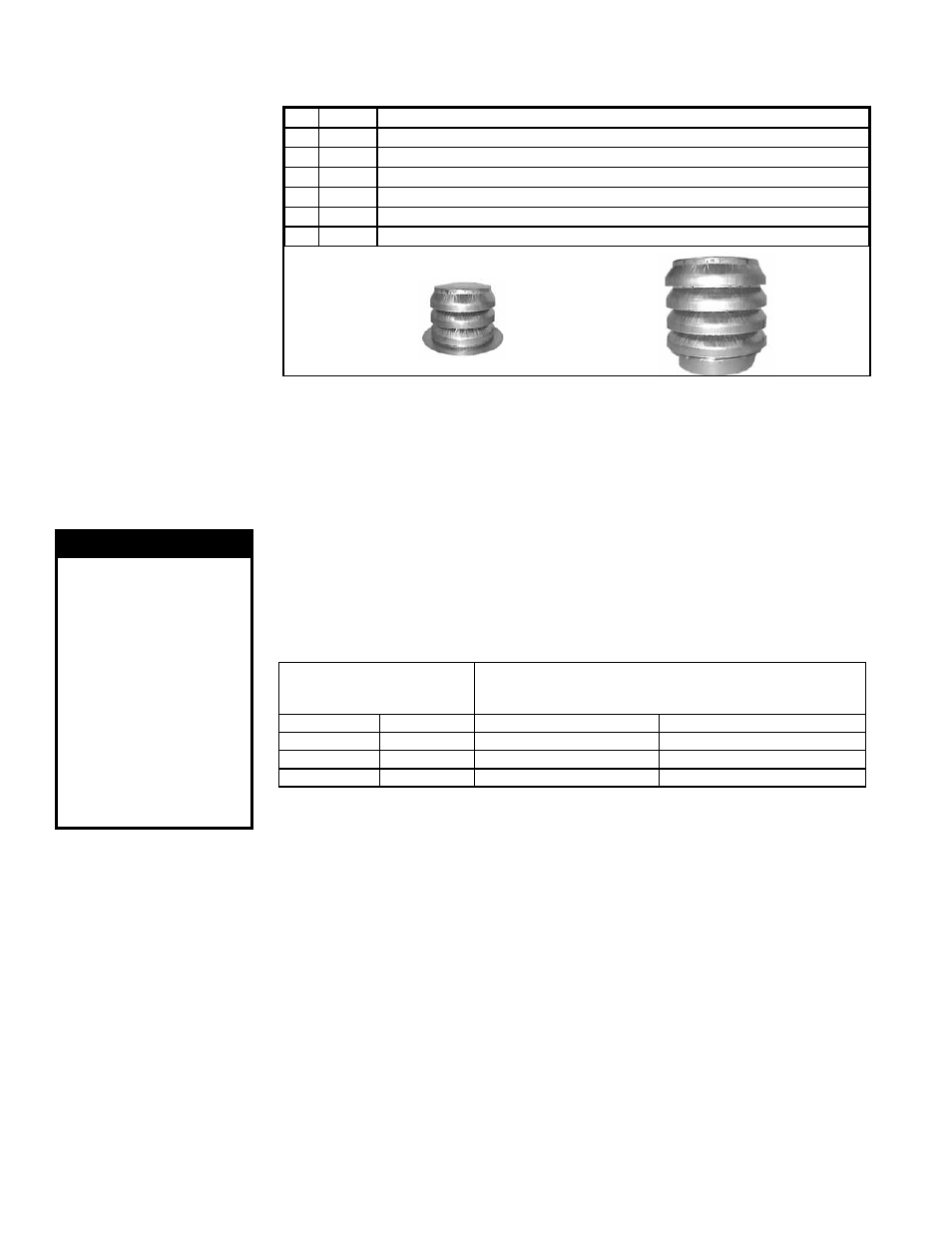
FIGURE 18 - Parts
in the Vertical Vent
Terminal/Combustion
Air Package (Option
CC2) - One required for
each furnace section.
Components Required
- Factory and Field
6.2.1.3 Vertical Vent Instructions - Model SSCBL
Field-supplied
installation
requirements:
• Vent pipes - see requirements, page 15.
• Combustion air pipes - see requirements, page 15.
• Taper-type pipe diameter reducers and/or increasers as required
• Thimble (a thimble is not required if wall is of non-combustible construction)
• Flashing
• Sheetmetal screws, tape, and sealant as required
Exhaust
(Vent)
Terminal,
P/N 53326
Combustion
Air Inlet,
P/N 53330
Qty
P/N
Description
1
205896 Complete Vertical Vent Kit (Same as Option CC2)
1
205885 Concentric Adapter Box Assembly (See FIGURE 13, page 17.)
1
53326 Exhaust (Vent) Terminal (illustrated below)
1
53330 Combustion Air (illustrated below)
2
207232 Brackets for attaching Concentric Adapter Box (FIGURE 20, page 23)
1
53335 Tube of High Temperature Silicone Sealant
Installation Instructions for Vertical Vent/Combustion Air Kit Option CC2
1. Determine the Location of the Vent Terminal(s). - Select a location away
from fresh air intakes, allowing space for each concentric adapter box inside. Vent
terminals must be located from adjacent buildings as shown in
FIGURE 24, page 25.
A vent terminal is required for each furnace section. When more than one vertical
concentric vent/combustion air terminal (Option CC2) is being installed, the minimum
spacing between vent centerlines is determined by the minimum outdoor design
temperature (most extreme outdoor condition at the installation site).
2. Install the Vent Pipe and Combustion Air Pipe Run(s). - Use the type of
pipe specified (Requirement No. 2, page 15), and comply with the attachment
requirements in Requirement No. 3, page 15. Length must comply with Requirement
No. 4, pages 15-16.
Seal all joints. Due to the high temperature,
do not enclose the exhaust pipes or
place pipes closer than 6" (152 mm) to combustible material. Provide supports for the
pipes. Extend the runs to close to the roof at the location(s) selected in Step 1 above.
Minimum Outdoor Design
Temperature
Minimum Spacing between Centerlines
of Vent Pipes in Vertical Combustion Air/Vent Terminals
(Option CC2)
°F
°C
inches
mm
31 or warmer
0 or warmer
36
914
-10 to 30
-23 to -1
60
1524
less than -10 less than -23
84
2134
6.2 Venting and
Combustion Air
(cont'd)
6.0 Mechanical
(cont'd)
3. Prepare hole(s) through the roof for the 8" (203mm) diameter combustion air
pipe. - A thimble may or may not be required depending on building construction and/
or local codes. The larger diameter combustion air pipe serves as clearance for the
vent pipe on non-combustible construction.
4. Prepare the Concentric Adapter Box
a) Attach the brackets to the box. Follow the instructions in FIGURE 20.
b) Attach the outside portion of the combustion air pipe to the box. Determine
the length of the combustion air pipe so that dimension ”X” in
FIGURE 21 is equal to
the bracket length, plus the roof thickness, plus anticipated snow depth, but does not
exceed 48“ (1219mm) or have less than 18” (457mm) of pipe above the roof. Attach
the inlet air pipe to the collar of the concentric adapter box with sheetmetal screws.
6.2.1 Separated-Combustion Model SSCBL (cont'd)
WARNING
All vent terminals
must be positioned
or located away from
fresh air intakes,
doors and windows to
preclude combustion
products from
entering occupied
space. Failure to
comply could result
in severe personal
injury or death and/or
property damage.