Reznor RPBL Unit Installation Manual User Manual
Page 25
Form I-SSCBL/RPBL, P/N 149159 R7, Page 25
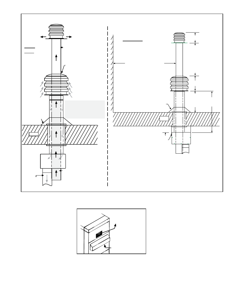
Flashing
(field-supplied)
Concentric
Adapter Box
Wall or
Adjoining
Building
6 ft (1.8M) minimum
9-3/8 (238mm)
11 (279mm)
*18
(457mm)
minimum
4 ft (1.2M)
maximum
Roof
*Inlet air cap must be at least 6
higher than anticipated snow depth.
2 (51mm) if roof is combustible
Attach box to roof with brackets.
12 (305mm) minimum
Cold Climate NOTE: In
geographic areas where
the design ambient is
-10°F or lower, this
minimum height is 24
(610mm).
(Top of Box)
Combustion
Air Pipe
Concentric
Adapter
Box
Roof
Double-wall Vent
(flue exhaust) Pipe
Combustion
Air Inlet
Vent (flue
exhaust) Terminal
Seal with silicone
sealant supplied
with the kit.
Flashing
(field-supplied)
Shaded area represents
required continuous (no
joints) section of double-
wall vent pipe. Section of
pipe may extend higher.
One-piece of Double-
Wall Vent Pipe
Use taper-type reducer
to attach to vent run
a maximum of 6
(152mm) from the box.
FIGURE 24 - Installation of Unit with Vertical Vent Terminal/Combustion Air Inlet (Option CC2)
Rear
View
Side View
Flue
Products
Outlet
Combustion
Air Inlet
FIGURE 25 - Flue Outlet
and Combustion Air
Inlet - Model RPBL
Optional Vertical Flue Discharge (Option CC3) for Model RPBL
These power vented furnaces are certified with four feet (1.2M) of vertical pipe attached
as shown in
FIGURES 26A and 26B. The distance is measured from the top of the unit
to the bottom of the vent cap. The option package includes the 5" vent cap, the adapter
assembly and the seal plate. (One package is required for each furnace section.) The
vent pipe and supports are field supplied. The straight pipe connecting the furnace to
the 90° elbow must be at least 18" (457mm) in length.
6.2.2 Venting Outdoor
Power Vented Model
RPBL
The screened flue gas and combustion air openings are located on the side of each
furnace section just above the control access panel (
FIGURE 25).
The positions of the openings discour-
age recirculation of combustion products
and provide for furnace operation in all
normal weather conditions.
Install a power-vented furnace so that
the flue discharge is
not directed at fresh
air inlets.