7 parameterisation of the operating modes – ebm-papst ECI-63.XX-K4 User Manual
Page 38
38
7 Parameterisation of the Operating Modes
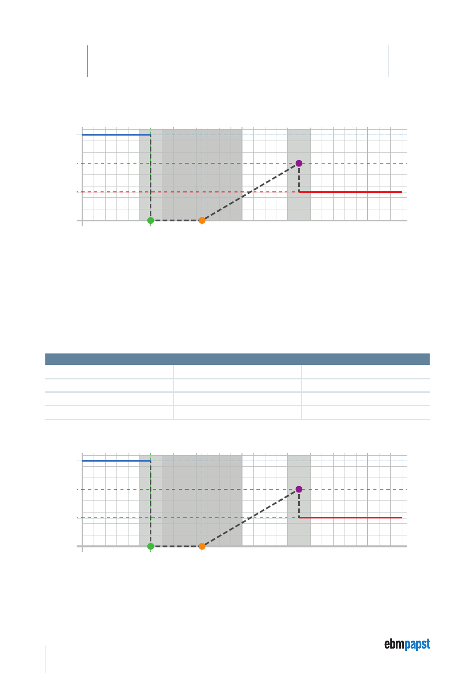
The characteristic curve can then take on this shape:
Y0
Y3
Y4
Y1
Y2
X1
X2
X3
Hysteresis 1
Target velocity
Hysteresis 2
Hysteresis 3
Normalised X axis
The speed values Y0…Y4 are given in rpm.
X values: Target value analog IN A1: 0 – 10 V corresponds 0 – 1023.
Target value PWM IN 1: 0 – 100 % corresponds X value 0 – 100.
Target value frequency IN 1: lower cut-off frequency (Parameter 0x3D) corresponds X value 0.
Target value frequency IN 1: upper cut-off frequency (Paramete r 0x3E) corresponds X value 1023.
7.3 Parameterisation of the maximum current characteristic
The maximum current characteristic can be defined via three interpolation points. A hysteresis can be set for each interpolation point. In
addition, an error current can be parameterised, which is used if an invalid X axis value results.
The maximum current characteristic is defined using the following parameters:
P11 – FE_Current_X1
P15 – FE_Current_Y1
P19 – Current_X1_Hyst
P12 – FE_Current_X2
P16 – FE_Current_Y2
P20 – Current_X2_Hyst
P13 – FE_Current_X3
P17 – FE_Current_Y3
P21 – Current_X3_Hyst
P14 – FE_Current_Y0
P18 – FE_Current_Y4
P22 – Error_Current
The characteristic curve can then take on this shape:
Y0
Y3
Y4
Y1
Y2
X1
X2
X3
Hysteresis 1
Target current
Hysteresis 2
Hysteresis 3
Normalised X axis