5 basic configuration, 3 product description – ebm-papst ECI-63.XX-K4 User Manual
Page 15
15
3 Product Description
3.5 Basic configuration
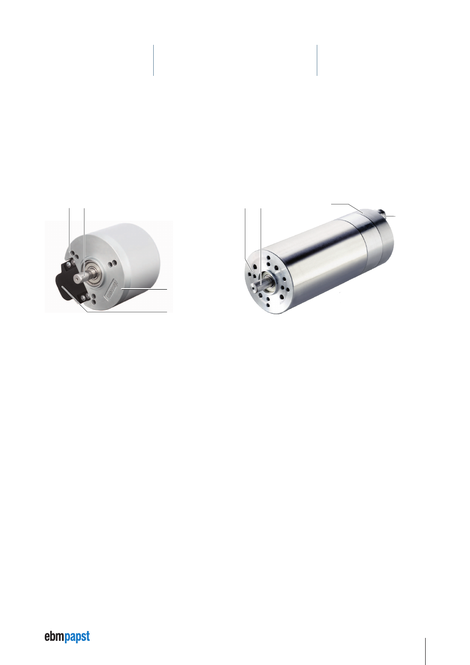
In the VDC-49.15-K4 drive system the control electronics (3) is attached on the motor output end (1). The connection cable is preinstalled in
the control electronics (3) in the factory. The motor housing on the output shaft (2) is formed as a flange with various drillholes for fixing and
attaching the transmission.
In the drive systems of the ECI-63.XX modular system K4 series, the motor housing and control electronics (3) are configured with same
diameter. All necessary electrical connections (4) are integrated in the control electronics (3). The motor housing is formed as a flange at the
output shaft (2) with various drillholes for fixing and attaching the transmission.
VDC-49.15-K4
eCI-63.XX-K4
2
1
4
3
3
4
1
2
1 Motor output side with fixing option or transmission attachment
2 Output shaft
3 Integrated power and control electronics
4 Power, signal and RS485 link