10 circuit diagram, 5 installation – ebm-papst ECI-63.XX-K4 User Manual
Page 28
28
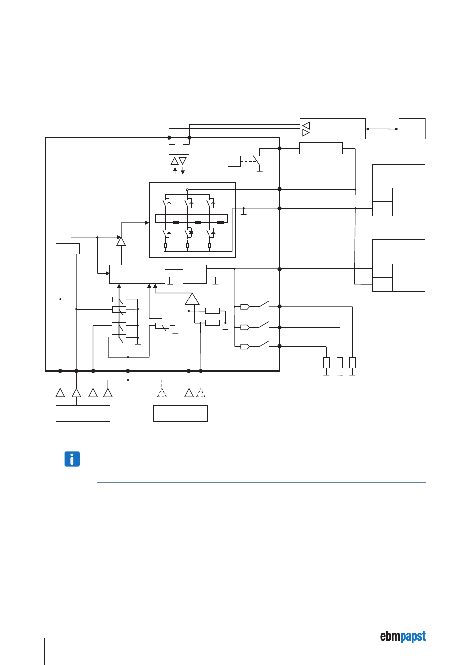
5 Installation
5.10 Circuit diagram
U
Logic
IN 2
Power Supply
„Power“
(+24 V / +48 V DC)
GND
+
Power Supply
„Logic“
(+24 V DC)
GND
+
Ballast
U
ZK
GND
µC
Ballast - Resistor
Logic-
SMPS
OUT 1
OUT 2
OUT 3*
Control
or
IN A
IN B
IN 1
Anal
og IN 1
Anal
og GN
D
Ana
lo
g I
N 2
IN 2
RS485
+
RS485
-
24 V (SPS)
Enable
Powerstage
0…10 V
Motor VDC-3-49.15-K4
Motor ECI-63.XX-K4
ebmpapst
RS485-Controller
Laptop
* The OUT 3 connection is only available for the ECI-63.XX-K4 drive systems.
NOTe
The user is responsible for external fusing of the power supply.
This manual is related to the following products: