7 parameterisation of the operating modes – ebm-papst ECI-63.XX-K4 User Manual
Page 37
37
7 Parameterisation of the Operating Modes
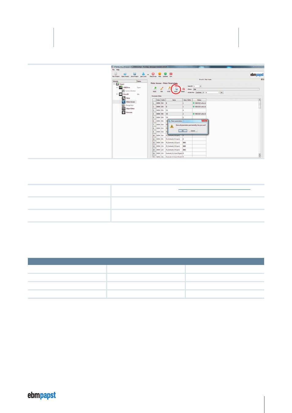
6 Save parameters: Save the parameters
written with the “store” command in the
“custom” memory area.
Commissioning (startup)
The following connections must be set up for the commissioning:
U
ZK
= supply voltage
IN A= On / Off (see IN A / B logic table,
see Chapter 8 Inputs and Outputs, page 77
here: Switch from free-wheeling to rotational direction cw (speed control)
GND = ground / earth
IN 1 = +24V (see logic table - fixed speeds)
here: Selection of N1
U
Logic
= supply voltage +24V
7.2 Parameterisation of the speed regulation characteristic
The speed regulation characteristic can be defined via three interpolation points. A hysteresis can be set for each interpolation point. In
addition, an error speed can be parameterised, which is used if an invalid X axis value results.
The speed regulation characteristic is defined using the following parameters:
P11 – FE_Speed_X1
P15 – FE_Speed_Y1
P19 – Speed_X1_Hyst
P12 – FE_Speed_X2
P16 – FE_Speed_Y2
P20 – Speed_X2_Hyst
P13 – FE_Speed_X3
P17 – FE_Speed_Y3
P21 – Speed_X3_Hyst
P14 – FE_Speed_Y0
P18 – FE_Speed_Y4
P22 – Error_Speed