5 braking chopper k4, 6 functional ground connection, 7 rs485 interface – ebm-papst ECI-63.XX-K4 User Manual
Page 26: 8 usb-can-rs485 adapter, 5 installation
26
5 Installation
5.5 Braking chopper K4
The task of the braking chopper is to convert the energy not required in case of fast speed changes. If the set voltage threshold is exceeded
the external resistor is switched on.
Chopper current
Recommended braking resistor
max. 10 A
24 V systems: >= 3.75 ohm
48 V systems: >= 5.6 ohm
NOTe
Braking resistor not included in the scope of supply.
The braking resistor must be tested and designed according to the use of the drive.
(Note maximum power loss!)
5.6 Functional ground connection
A functional ground connection must be provided for equipotential
bonding.
Functional ground connection
on the ECI-63.XX-K4 drive
5.7 RS485 interface
The RS485 interface is used as the parameterisation and diagnostic interface. The “Kickstart” PC software can be used for operation of the
interface. A PC and the ebm-papst USB-CAN-RS485 adapter are required for this.
NOTe
The “Kickstart” PC software only operates correctly with the ebm-papst USB-CAN-RS485 adapter.
If you use another USB-CAN-RS485 adapter, you will need the relevant software.
NOTe
The bus interfaces are wired by the user. Depending on the topology, the line termination (resistors) must be realised by
the user.
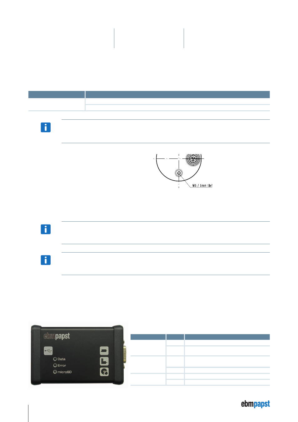
5.8 USB-CaN-RS485 adapter
The USB-CAN-RS485 adapter is required as an accessory for the ebm-papst “Kickstart” software, in order to connect the PC with the K4
drive. The adapter can be ordered under Material No. 914 0000 400.
Functional description of the LeD displays
LED name
Colour
Function assignment
Data
red
• No assignment.
green
• Active data transfer via the USB CAN-RS485
adapter.
Error
red
• No response following request to K4.
• Receipt of a faulty data package.
green
• Received data is ok.
microSD
red
• No assignment.
green
• Access to the memory card.