5 installation, 1 notes, 2 installing the drive – ebm-papst ECI-63.XX-K4 User Manual
Page 22: 1 determine screw length, 2 prepare the mounting plate, 2 installing the drive caution, Caution
22
5 Installation
This chapter describes the mechanical and electrical connection of the drive systems.
5.1 Notes
The drives must be checked for visible damage before installation. Damaged drive system must not be installed.
The drives must be fixed onto a flat surface with at least 4 screws. The screws must be secured with suitable measures against loosening.
Use thread-forming screws to DIN 7500 for the fixing.
5.2 Installing the drive
CaUTION
Risk of damage!
When the drives are installed in the motor housing it can be damaged by high radial loads, if the tightening torque applied
to the fixing screws is too high or if the fixing screws are too long.
f
Do not load the motor shaft, either radially or axially, with more than 150 N.
f
Tighten fixing screws M4 with 3
±0.2
Nm maximum, M5 with 4
±0.2
Nm maximum.
f
Do not exceed the specified maximum length of the fixing screws (
see Chapter “5.2.1 Determine screw length”
).
CaUTION
Risk of damage to electronic components!
The discharge of static charge during installation of the drives can damage the electronic component.
f
Use ESD protective equipment during installation.
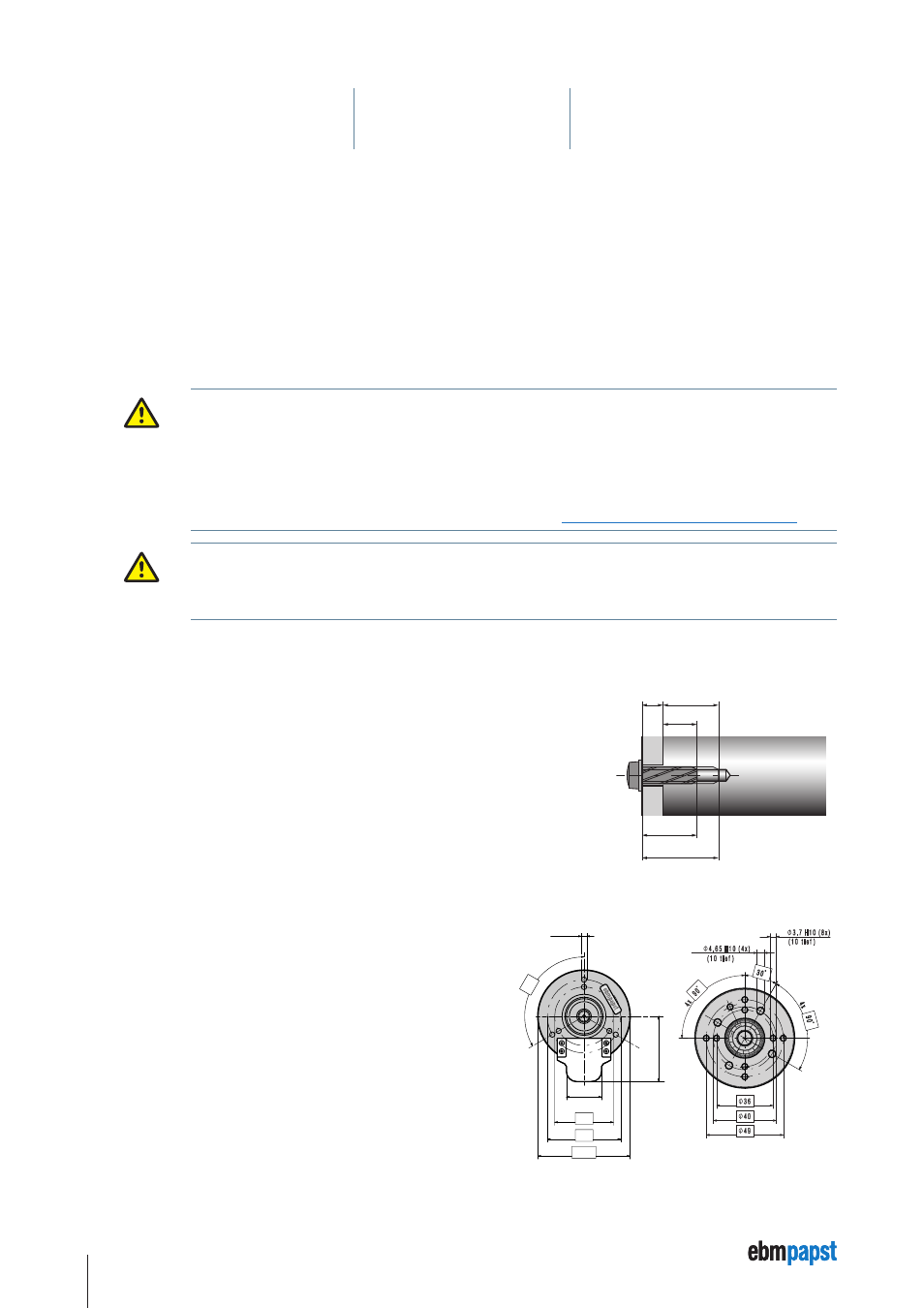
5.2.1 Determine screw length
A minimum screw length S
min
is required for safe and reliable fixing of the motors.
The maximum allowable screw length S
max
prevents damage to the motor.
Minimum screw length S
min
=
Minimum depth of engagement E
min
6.5 mm + material thickness X of the mounting plate.
Maximum screw length S
max
=
Maximum depth of engagement E
min
8.0 mm + material thickness X of the mounting plate.
X
E
max
E
min
S
min
S
max
5.2.2 Prepare the mounting plate
Only use the drillholes on the output side of the motors housing to fix the drive.
To this end, transfer the necessary drillholes for the centring collar of the motor,
pitch circle and size of the fixing holes onto the mounting plate and drill (see
sketch).
±0,2
Ш63
Ш40
Ш50
24
±0,2
44,65
±0,5
3x
120˚
Ø3,7
±0,04
Sketch of fixing holes, motor
housing VDC-3-49.15-K4
Sketch of fixing holes, motor
housing ECI-63.XX-K4