4 connection descriptions, 1 connection cable vdc-3-49.15-k4, 2 motor connection socket eci-63.xx-k4 – ebm-papst ECI-63.XX-K4 User Manual
Page 24: 5 installation
24
5 Installation
5.4 Connection descriptions
NOTe
• The connection cable of the VDC-3-49.15-K4 motors is pre-installed on the motor in the factory.
• The ECI-63.XX-K4 motors have a 15 pin connector M16 (12+3) on the motor. This is used for the connection of a
connector variant connector cable or for the separately supplied cable harness of the Litz wire variant.
5.4.1 Connection cable VDC-3-49.15-K4
The pin assignment of the connection socket is as follows:
AWG 16
AWG 24
Litz
Connection
ID
AWG
Cross-section
Blue
Ballast
Ballast resistance
16
1,3 mm
2
Brown
U
ZK
Power supply
16
1,3 mm
2
Black
GND
Power / signal GND
16
1,3 mm
2
Green
U
Logic
Logic supply + (24 V)
24
0,22 mm
2
White
RS485 +
Progr. Bus
24
0,22 mm
2
Grey
RS485 -
Progr. Bus
24
0,22 mm
2
red
Analog IN 1
0 …10 V (differential)
24
0,22 mm
2
Yellow
Analog GND
GND for analog IN 1 (differential)
24
0,22 mm
2
Violet
IN 1
NPN 24V
24
0,22 mm
2
Black
IN 2
NPN 24V / Analog
24
0,22 mm
2
Red-blue
IN A
NPN 24V
24
0,22 mm
2
Grey-pink
IN B
NPN 24V
24
0,22 mm
2
Brown
OUT 1
PNP 24V
24
0,22 mm
2
Pink
OUT 2
PNP 24V
24
0,22 mm
2
Blue
GND
Signal-GND
24
0,22 mm
2
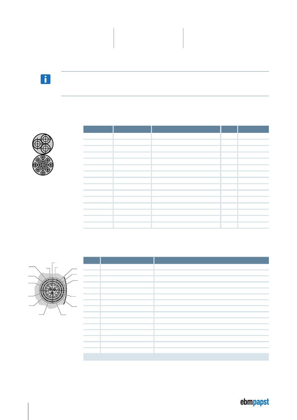
5.4.2 Motor connection socket ECI-63.XX-K4
The pin assignment of the connector is as follows:
12
11
C
9
B
A
8
7
6
5
4
3
2
1
10
Pin
Connection
ID
1
IN A
NPN 24 V
2
IN B
NPN 24 V
3
IN 1
NPN 24 V
4
IN 2 *
NPN 24 V
5
OUT 1
PNP 24 V
6
OUT 2
PNP 24 V
7
OUT 3
PNP 24 V
8
Analog IN 1
0 …10 V (differential)
9
Analog GND
GND for analog IN 1 (differential)
10
RS485 +
Progr. Bus
11
RS485 –
Progr. Bus
12
U
Logic
Logic supply + (24 V)
A
Ballast
Ballast resistance
B
U
ZK
Power supply
C
GND
Power / signal GND
* Can also be parameterised as analog IN 2.