AERCO SmartPlate User Manual
Page 92
SmartPlate Installation, Operation & Maintenance Manual
APPENDIX A – MODBUS CONTROL AND COMMUNICATION
Page 92 of 138
AERCO International, Inc.
100 Oritani Dr. Blauvelt, NY 10913
OMM-0069_0E
PRI: 11/26/2013
Phone: 800-526-0288
SP-100
A.1 TEMPERATURE CONTROLLER (EUROTHERM 2408) PROCEDURES
The following paragraphs provide the procedures to add a Modbus Communication board to the
Temperature Controller and change communication addresses.
A.1.1
Adding a Communication Board to the Temperature Controller
Parts Needed:
a. ECS/SP Control Box Assembly, P/N: 69096-[ ]
b. Temperature Indicating Controller, P/N: 64008-[ ]
c. Communications Board, P/N: 64009-[ ]
Procedure:
1. Turn off power to ECS/SP Control Box Assembly
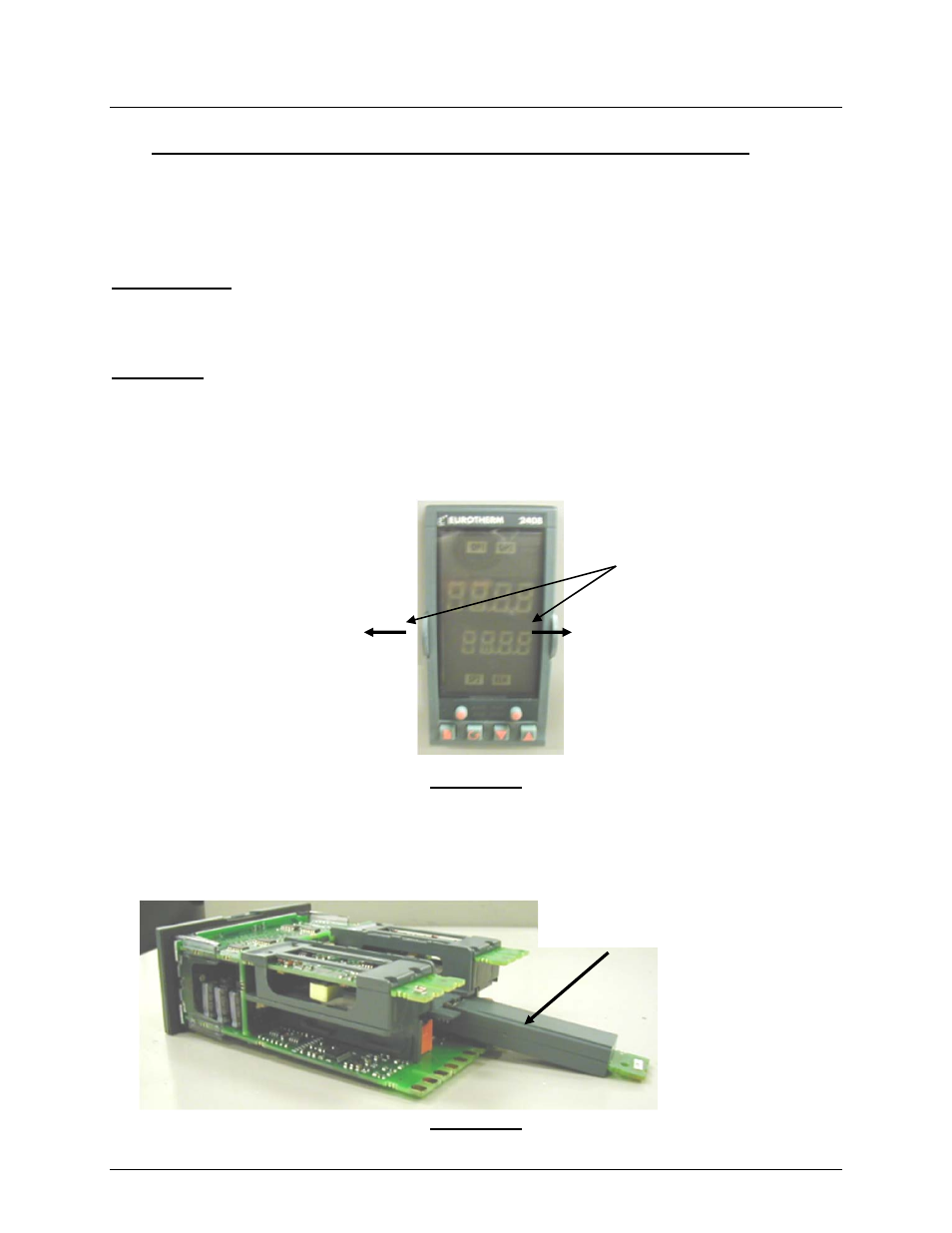
2. Slide out Temperature Indicating Controller (P/N: 64008) from Control Box Assembly by
gently pushing the indicated latching ears to the side (See Figure A-1).
Figure A-1
3. Slide Communications Board (P/N 64009-[ ]) into Temperature Indicating Controller slot
(COMMS 1). See Figure 2. Make sure to push Communications Board all the way in to
ensure it is firmly seated in its slot.
Figure A-2
COMMUNICATION
S
LATCHING
EARS (2)