AERCO SmartPlate User Manual
Page 28
SmartPlate Installation, Operation & Maintenance Manual
CHAPTER 4 – ADJUSTMENT
Page 28 of 138
AERCO International, Inc.
100 Oritani Dr. Blauvelt, NY 10913
OMM-0069_0E
PRI: 11/26/2013
Phone: 800-526-0288
SP-100
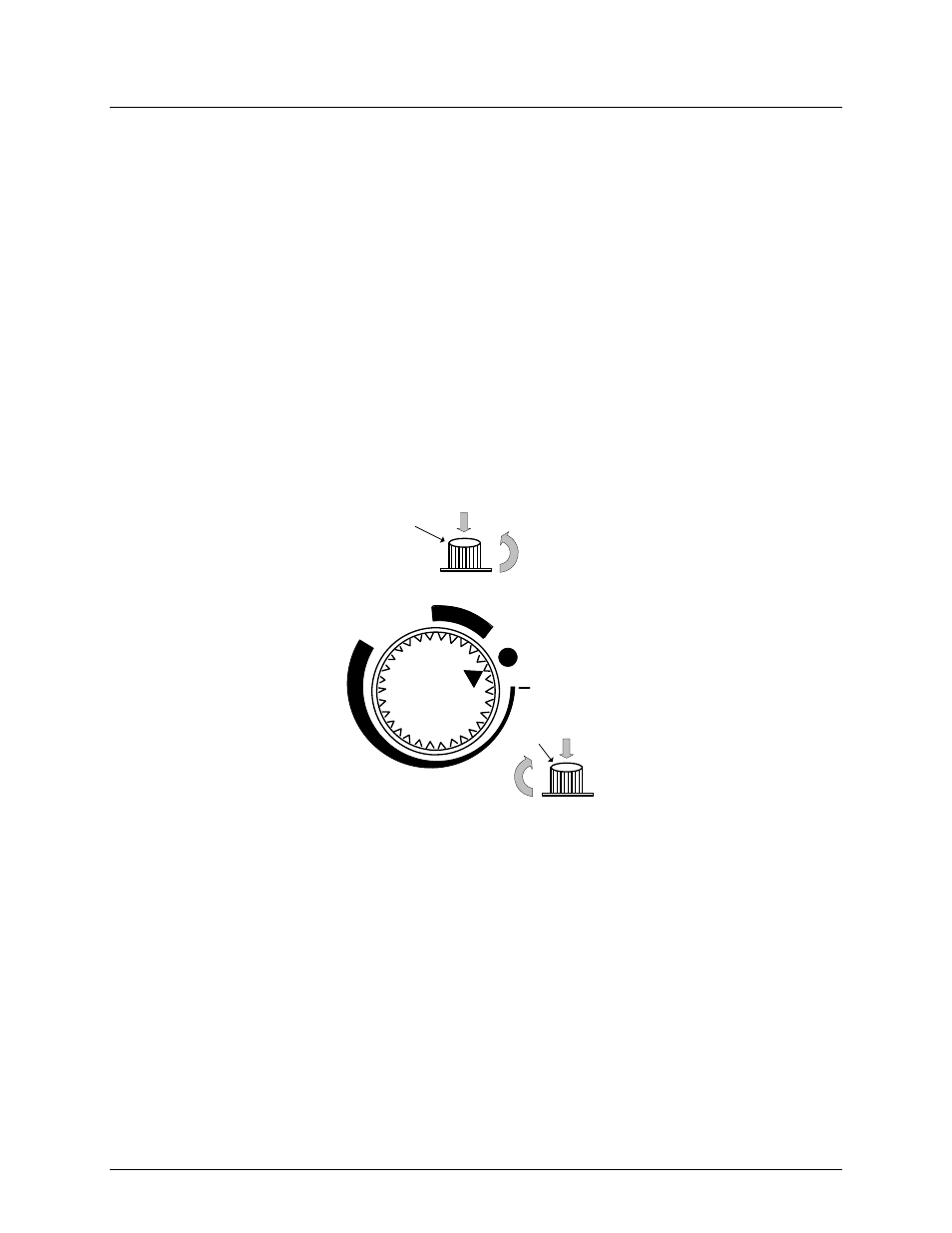
4.2.2 Manual Control of 3-Way Valve – Removable Handwheel to Hamper
Tampering
If desired, the control path (A-to-AB) of the Control Valve, (Siemens, MXG-461) can be opened
manually up to 95% of full-stroke. Refer to Figure 4-3 and proceed as follows:
1. Remove the water heater from service prior to using the manual operating mode.
2. Press the handwheel inward and rotate it clockwise to the MANUAL position. This will
disable the 0 to 10 VDC control signal from the ECS/SP Temperature Controller. The
Valve can now be mechanically rotated. The temperature control system is now disabled.
Be sure to return to the AUTO mode prior to returning the system to heating service use
(see step 4).
3. To disable automatic control of the Valve, press the handwheel inward and rotate it
counterclockwise to the OFF position. This will close the Valve.
4. To set the Valve for automatic (AUTO) operation, rotate the handwheel to the AUTO
position. The handwheel will pop up when in the AUTO position, thereby allowing it to be
controlled by the ECS/SP Temperature Controller.
AUTO
OFF
MANUAL
CCW
CW
Push down
to rotate
Push down
to rotate
Figure 4-3. Control Valve Auto, Manual and Off Positions
The SmartPlate Electronic Control System (ECS/SP) is preset at the setpoint temperature
specified on the Sales Order. The over-temperature alarm limit is normally set 20°F above the
specified setpoint. If no setpoint or over-temperature alarm limit is specified, the ECS/SP will be
set to the Factory Default values of 140°F (setpoint) and 160°F (over-temperature alarm limit). If
changes are required, the setpoint and over-temperature alarm limits can be easily changed.
This is accomplished using the controls provided on the Temperature Controller and the Over-
Temperature Switch contained in the Control Box shown in Figure 4-4. These items can be
viewed through the window on the front door of the Control Box. To access these controls and
adjust the setpoint or over-temperature alarm limit, open the hinged Control Box door. Proceed
as indicated in paragraphs 4.3.1 or 4.3.2 to adjust the required parameters: