AERCO SmartPlate User Manual
Page 14
SmartPlate Installation, Operation & Maintenance Manual
CHAPTER 2 – INSTALLATION
Page 14 of 138
AERCO International, Inc.
100 Oritani Dr. Blauvelt, NY 10913
OMM-0069_0E
PRI: 11/26/2013
Phone: 800-526-0288
SP-100
CAUTION
For Single-Wall Models, DO NOT attempt to reposition the
ECS/SP Control Box with the panel displays facing the SmartPlate
Heater Piping Assembly. Attempting to do so will prevent the
Control Box door from being fully opened due to the location of the
SmartPlate lifting tabs (Figure 2-2 a).
2.3.3 Repositioning ECS/SP Control Box
If required, the front panel displays of the ECS/SP Control Box can be repositioned from the
default left-side of the SmartPlate (Figure 2-2) to either the right side or rear of the SmartPlate to
optimize viewing of the panel displays. Repositioning of the Control Box is accomplished as
follows:
1. Power off.
2. Disconnect external cables at their respective connections (Molex).
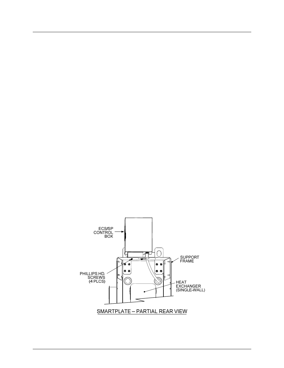
3. From the rear of the SmartPlate Heater (Figure 2-3), remove the four Phillips head screws
securing the base of the Control Box to the SmartPlate frame assembly.
4. Position the Control Box to the desired orientation to provide easy viewing of the control
panel displays.
5. Ensure that all power and control wiring are of sufficient length to prevent undue stress on
the wiring connections. Reposition wiring harnesses as necessary.
6. Replace the four Phillips head screws removed in step 1.
7. Apply power if previously connected.
8. This completes the repositioning of the ECS/SP Control Box.
Figure 2-3. Repositioning ECS/SP Control Box