AERCO SmartPlate User Manual
Page 87
SmartPlate Installation, Operation & Maintenance Manual
CHAPTER 8 – CORRECTIVE MAINTENANCE
OMM-0069_0E
AERCO International, Inc.
100 Oritani Dr. Blauvelt, NY 10913
Page 87 of 138
SP-100
Phone: 800-526-0288
PRI: 11/26/2013
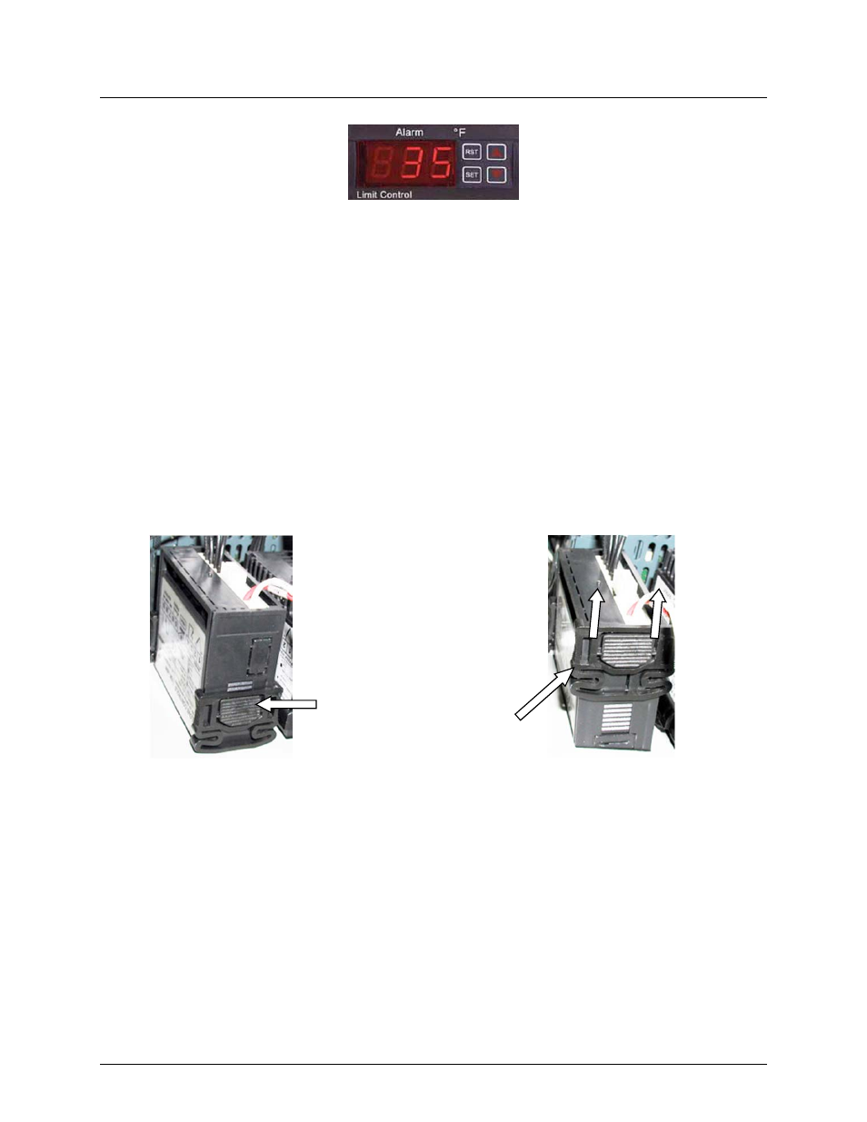
Figure 8-27a. Over-Temperature Switch & Temperature Indicator
1. Open the Control Box door to locate the Switch or Indicator to be replaced.
2. Loosen the captive screw on the recessed panel behind the door. Open the swing-down
panel to access the Switch/Indicator wiring connections and panel retaining clips.
3. Remove the Switch/Indicator rear cover and loosen the terminal wiring connection screws.
Disconnect the wires.
4. To remove the Over-temperature Switch assembly, push in tab of each of two side
retaining clips (Figure 8-27b), slide toward rear and remove.
5. Insert the replacement Over-Temperature Switch or Temperature Indicator into the panel
cutout.
6. Slide the removable retaining clip onto the replacement Switch/Indicator from the rear.
Push the retaining clip forward until the Switch/Indicator is firmly secured in the panel
cutout.
7. Reconnect the wiring to the rear of the unit and tighten the terminal screws. Replace the
terminal cover.
8. If the replaced unit is an Over-temperature Switch, set the desired over-temperature alarm
limit using the adjustment procedures in Chapter 4, Section 4.3.2.
9. Following adjustment (if necessary), raise and secure the swing-down panel. Close and
secure the Control Box door.
8.17 24 VAC STEP-DOWN TRANSFORMER REPLACEMENT
The 24 VAC Transformer is mounted on the back interior wall of the Control Box (Figure 8-28,
View D-D). Replacement is accomplished as follows:
1. Open the Control Box door and loosen the captive screw on the recessed panel behind
the door.
To uninstall, push tab to
release clip retainer. Slide
clip back and off. Remove
assembly through front
panel.