5 smartplate electrical wiring connections, Chapter 2 – installation – AERCO SmartPlate User Manual
Page 16
SmartPlate Installation, Operation & Maintenance Manual
CHAPTER 2 – INSTALLATION
Page 16 of 138
AERCO International, Inc.
100 Oritani Dr. Blauvelt, NY 10913
OMM-0069_0E
PRI: 11/26/2013
Phone: 800-526-0288
SP-100
2.5 SMARTPLATE ELECTRICAL WIRING CONNECTIONS
The ECS/SP Control Box and all other ECS/SP components are installed on the SmartPlate
Water Heater prior to shipment from the factory. Therefore, electrical connections to the
SmartPlate ECS/SP basically consist of connecting external AC power to the ECS/SP Control
Box. The system can be powered by a single-phase AC voltage of 120 VAC, 60 Hz or 220 VAC,
50 Hz. However, if the SmartPlate ECS/SP was ordered with the Modbus Communication
option, several additional signal lead connections will need to be made inside the Control Box.
These signal leads will permit the ECS/SP to be controlled by an external Energy Management
System (EMS), Building Automation System (BAS), or Computer. Proceed as follows:
NOTE
Following installation, a lock (Not Supplied) can be installed on the
front door of the Control Box, if desired, to prevent unauthorized
access to ECS settings.
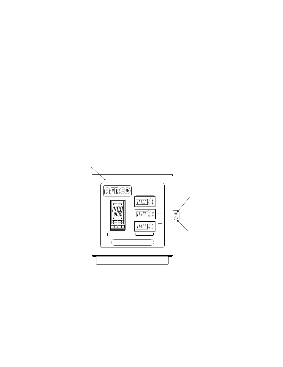
1. Loosen the captive screw on the right-front portion of the Control Box (Figure 2-4) to open
the hinged panel door.
TEMP CONTROLLER
HOLD
RUN
AUTO
MAN
2408
OVER TEMP SWITCH
BOILER WATER TEMP
OUT
IN
SET
F
SET
F
SET
F
WATER HEATER
PANEL
DOOR
CAPTIVE
SCREW
HOLE FOR
LOCK
Figure 2-4. ECS/SP Control Box Front View
2. Next, open the door and loosen the captive screw at the top of the recessed panel (Figure 2-
5).