AERCO SmartPlate User Manual
Page 12
SmartPlate Installation, Operation & Maintenance Manual
CHAPTER 2 – INSTALLATION
Page 12 of 138
AERCO International, Inc.
100 Oritani Dr. Blauvelt, NY 10913
OMM-0069_0E
PRI: 11/26/2013
Phone: 800-526-0288
SP-100
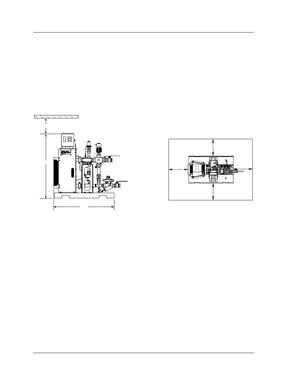
local building codes require additional clearances, these codes shall supersede AERCO’s
recommendations.
Sides: 24 in. (61 cm)
Front:
24 in. (61 cm)
Rear: 24 in. (61 cm)
Top: 12 in. (30.5 cm)
All water piping and electrical conduit must be arranged so that it does not interfere with the
removal of any SmartPlate Heater assemblies/parts or inhibit service or maintenance of the unit.
24"
24"
24"
24"
12"
52"
49"
Figure 2-1. SmartPlate Water Heater Clearances
CAUTION
While packaged in the shipping container, the heater must be
move using a forklift or pallet jack. After unpacking, the heater
should be lifted and moved using the lifting tabs (single-wall
model), or frame cutouts (double-wall model) provided on the
heater. Alternately, a forklift or pallet jack may be used to move
the unit by inserting the tines through the cutouts in the heater
base (Figure 2-1). Refer to the information in the following
paragraph.
2.3.2 Setting the Unit
If anchoring the unit, refer to Appendix F for anchor locations. SmartPlate Single-Wall Models
contain two lifting tabs at the top of the frame assembly (Figure 2-2 a). Double-Wall Models
contain two round cutouts on the frame plate and two on the pressure plate of the heat
exchanger (Figure 2-2 b). Use these tabs or cutouts to lift and move the unit.