Chapter 2 – installation – AERCO SmartPlate User Manual
Page 17
SmartPlate Installation, Operation & Maintenance Manual
CHAPTER 2 – INSTALLATION
OMM-0069_0E
AERCO International, Inc.
100 Oritani Dr. Blauvelt, NY 10913
Page 17 of 138
SP-100
Phone: 800-526-0288
PRI: 11/26/2013
TEMP CONTROLLER
HOLD
RUN
AUTO
MAN
2408
OVER TEMP SWITCH
BOILER WATER TEMP
OUT
IN
SET
F
SET
F
SET
F
PANEL CAPTIVE
SCREW
WATER HEATER
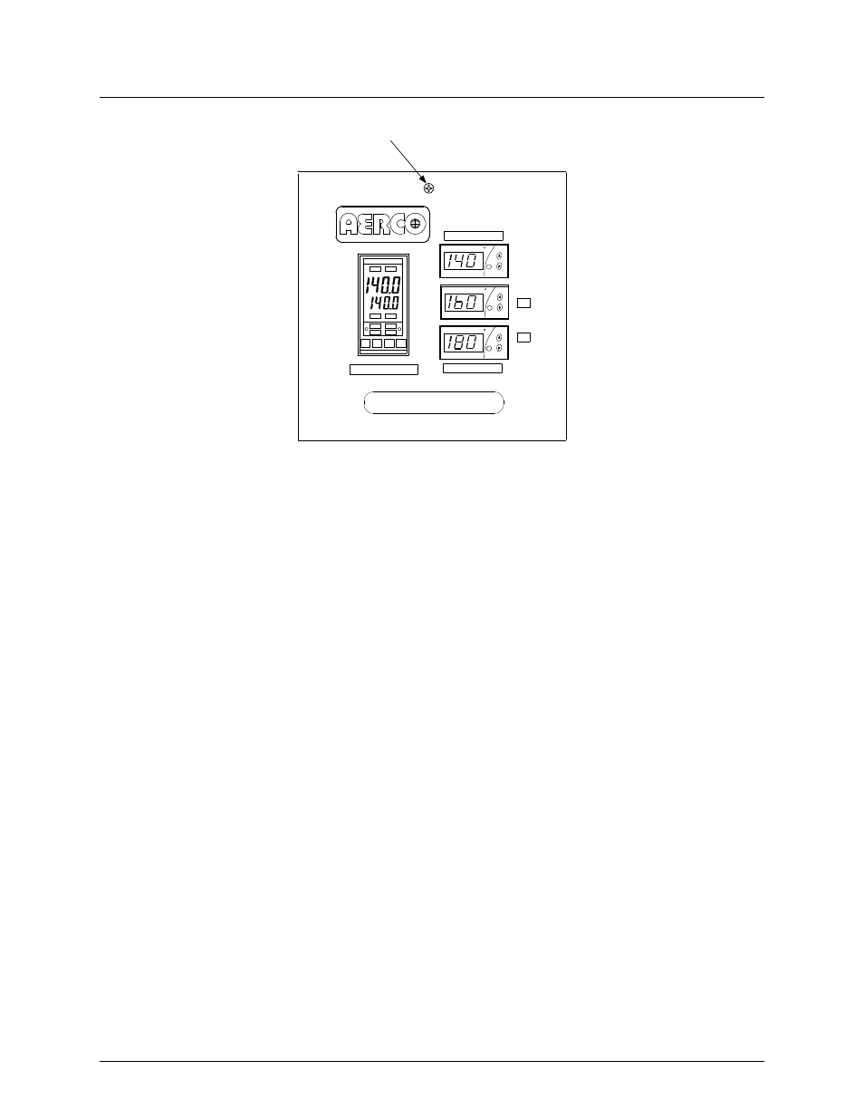
Figure 2-5. Recessed Panel Behind ECS/SP Control Box Door
3. Swing down the recessed panel to access Terminal Block TB-2 on the bottom interior
surface of the Control Box shown in Figure 2-6.
NOTE
Use 14 to 18 AWG wire for AC power wiring connections to the
SmartPlate ECS/SP Control Box.
4. Feed the external 120/220 VAC power leads through the cutout labeled “POWER IN” on the
bottom of the Control Box.
5. Connect the LINE, NEUTRAL and GROUND leads to the TB-2 terminals shown in Figure 2-
6.
6. Check the connection of wire #100 on the right side of TB-2 to ensure the power is routed to
the proper connection for the 24 VAC transformer. If the incoming power is 120 VAC/60 Hz,
wire #100 should be connected to the terminal with a black wire and the orange wire should
have nothing connected to its terminal. Conversely, if the incoming power is 220 VAC/50 Hz,
wire #100 should be connected to the terminal with the orange wire and the black wire left
unconnected.