AERCO SmartPlate User Manual
Page 19
SmartPlate Installation, Operation & Maintenance Manual
CHAPTER 2 – INSTALLATION
OMM-0069_0E
AERCO International, Inc.
100 Oritani Dr. Blauvelt, NY 10913
Page 19 of 138
SP-100
Phone: 800-526-0288
PRI: 11/26/2013
CAUTION
DO NOT route Modbus communication wiring in the same conduit
as power wiring. Attempting to do so may result in excessive noise
on the signal lines. Also, ensure that the RS232 or RS485 signal
cable connections do not exceed the following lengths:
RS232 Cable: 50 feet maximum
RS485 Cable: 4,000 feet maximum
8. To permit Modbus control of the ECS/SP, refer to Table 2-2 and connect the appropriate
wire leads to the Temperature Controller terminals listed. Refer to the Temperature
Controller (Eurotherm 2408) pinouts shown in Figure 2-7 to locate the required terminals.
Also, refer to Appendix A for instructions on how to change the Temperature Controller
Modbus address and for a listing of active Modbus data addresses for the 2408 Controller.
In addition, the Eurotherm documents referenced in this Appendix provide additional
communication information related to Modbus.
NOTE
The complete wiring diagram for the SmartPlate Electronic Control
System is provided in Appendix B of this Instruction Manual. In
addition, the wiring connections for Control Box Terminal Blocks
TB-1 and TB-2 are also provided for reference purposes.
NOTE
AERCO recommends that shielded, twisted-pair cable be used for
communication wiring. Examples of suitable wiring are: Belden
9841, 8761, 3105A, or equivalent.
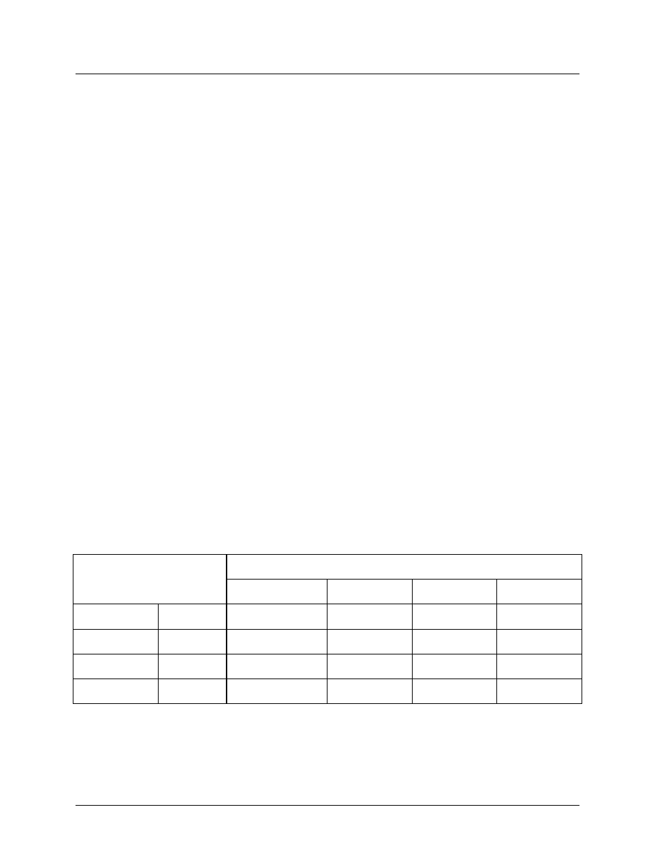
Table 2-2. Modbus Communication Signal Connections
2408 TEMP. CONTROLLER
COMPUTER CONTROL CABLE
RS232/9-PIN
RS232/25-PIN
RS485
SIGNAL NAME
PIN NO.
SIGNAL NAME
PIN NO.
PIN NO.
PIN NO.
GROUND HD
GROUND
5
7 GROUND
RECEIVE HE
TRANSMIT
3
2 A(-)
TRANSMIT HF
RECEIVE
2
3
B(+)