Cub Cadet 8454 User Manual
Page 42
CHAPTER 2 8454
2-20
D569-W02 May-2003
569W238A
569W237A
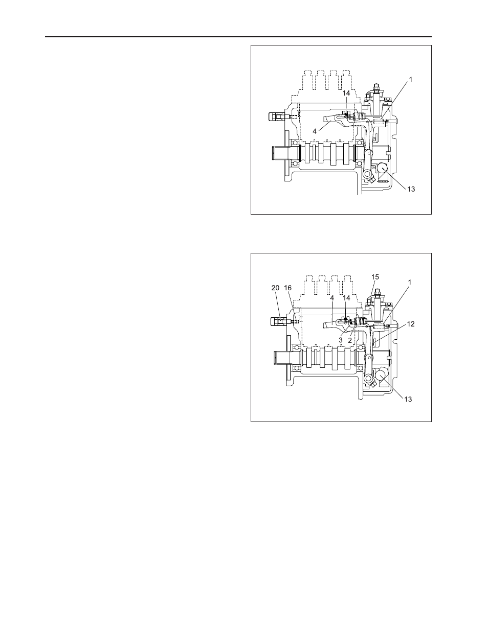
b. Operation of Governor
a) At start
The steel balls (13) have no centrifugal force. As the
fork lever 1 (4) is pulled by the start spring (1), the
control rack (14) moves to the maximum injection posi-
tion. At start, the sufficient injection of the fuel enables
easy starting.
(1) Start Spring
(13) Steel Ball
(4) Fork Lever 1
(14) Control Rack
b) At idling
At the idling position of the speed control lever (15), the
governor spring 1 (2) is free and the governor spring 2
(3) only acts slightly. The governor sleeve (12) is
pushed leftward by a centrifugal force of steel ball (13).
Therefore, the fork lever 1 (4) and control rack (14) are
moved to the rear by the governor sleeve (12) and then
the idling adjusting spring (16) is compressed by the
control rack (14). As a result, the control rack (14) is
kept at a position where the centrifugal force of steel
ball (13) and forces of the start spring (1), governor
spring 2 (3) and idling limit spring are balanced, pro-
viding stable idling.
IMPORTANT:
•
The idling speed has been factory-set. The idling
adjusting screw (20) and spring (16) should not be
disassembled and readjusted.
(1) Start Spring
(13) Steel Ball
(2) Governor Spring 1
(14) Control Rack
(3) Governor Spring 2
(15) Speed Control Lever
(4) Fork Lever 1
(16) Idle Adjusting Spring
(12) Governor Sleeve
(20) Idle Adjusting Screw