Cub Cadet 8454 User Manual
Page 207
HYDRAULIC SYSTEM
6-13
D569-W02 May-2003
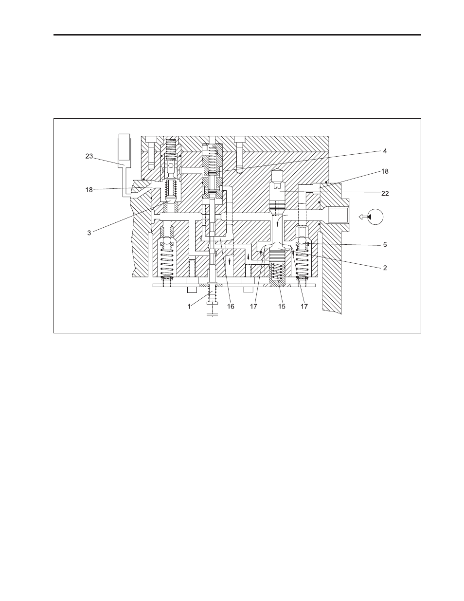
3. Operation Principle
Since the control valve of the hydraulic cylinder is avail-
able to control oil flowing in and out of the hydraulic
cylinder so to control the implement up and down at a
constant speed regardless of the implement load, high
work performance can be achieved without impact,
along with the operation principle classified into
3 phases of neutral, delivery and discharge.
a. Neutral Phase
In this phases the control valve keeps on pressure the
oil contained in the cylinder thus allowing the oil com-
ing from the pump flow freely to the tank.
In this phase the control spool (1) is in such a position
to connect the chamber (15) directly to the discharge
through hole (16).
The oil coming from the pump will thus be able to move
downward the small regulator piston (2) and thus flow
to the chamber (22) and by opening the holes (17) it
will flow to the tank.
(1) Spool
(6) Fixed Throat
(2) Piston
(7) Safety Valve
(3) Check Valve
(8) Regulator
(4) Valve
(15) Chambers
(5) Relief Valve
(16) Hole
(17) Hole
(22) Chamber
(18) Annular Duct
(23) Cylinder Chamber
(19) Annular Duct
(24) Hole
(20) Hole
(25) Hole
(21) Hole
The oil contained in the cylinder (Chamber 23) is kept
on pressure by the check valve (3), by the discharge
valve (4) and by the relief valve (5) connected to the
cylinder by annular duct (18) thus holding the load ap-
plied to the lifting.
The relief valve (15) secures protection from any pos-
sible overpressure.
569W610A