Cub Cadet 8454 User Manual
Page 141
TRANSMISSION SYSTEM
4-37
D569-W03 June-2003
•
When assembling, let the oil groove
of the thrust collar faced toward the
gear.
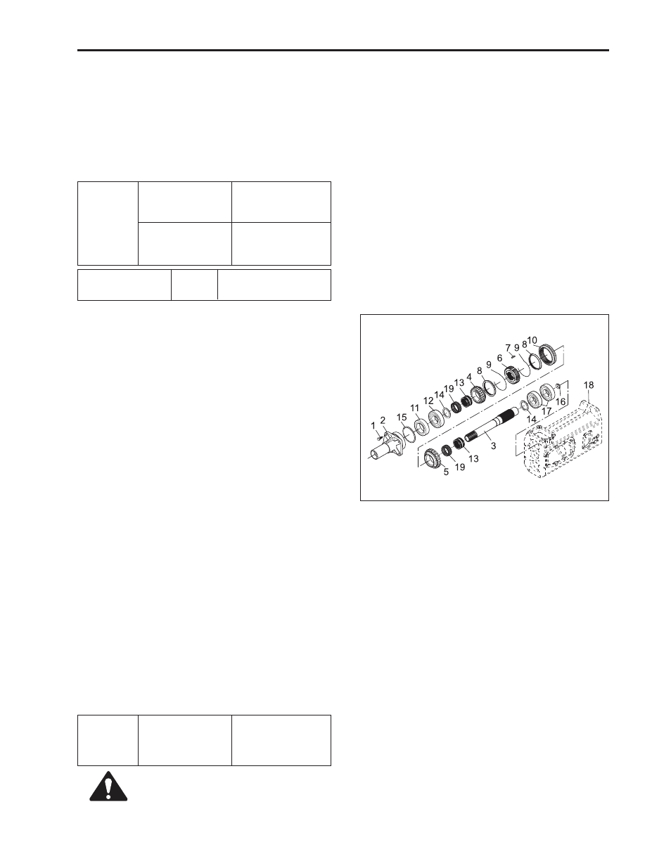
I. SHUTTLE SHAFT SECTION
a . To Disassembling
1. Remove clutch lever, release hub and release fork.
2. Loosen inlet bolt (1) of the propeller shaft case and
remove propeller shaft case (2).
3. Draw out shuttle shaft (3) to the front of the middle
case.
b. To Assemble
1. Install 6008 ball bearing (17) on middle case (18).
2. Install oil seal (16) on the inner bore of shuttle shaft
(3) and apply grease.
3. Sub-assemble synchro hub (6), synchronizer key
(7), spring (9) and shifter (10).
4. Locate shuttle shaft (3) on the assembling area of
middle case (18) and fix inner ring (13), 29 gear (5),
needle bearing (19), synchronizer ring (8) and syn-
chro hub which have been sub-assembled in due
order, and then install shuttle shaft (3) on ball bear-
ing (17) after inserting thrust collar (14).
5. Install needle bearing (19) and inner ring (13) on
the inner bore of 24 gear (4) of the shuttle shaft.
6. Sub-assemble oil seal (19), ball bearing (12) and
O-ring (15) on propeller shaft case (2), and apply
grease.
7. After inserting thrust collar (14) into shuttle shaft
(3), place the sub-assembly of propeller shaft case
(2) in shuttle shaft (3) to tighten 4 washer mounting
bolts (1) on middle case (18).
(1) Bolt
(2) Propeller Bearing Shaft Case
(3) Shuttle Shaft
(4) 29 Gear
(5) 24 Gear
(6) Synchro Hub
(7) Synchronizer Key
(8) Synchronizer Ring
(9) Spring
(10) Shifter
(11) Ball Bearing
(12) Ball Bearing
(13) Inner Ring
(14) Collar
(15) O-Ring
(16) Oil Seal
(17) Ball Bearing
(18) Middle Case
(19) Needle Bearing
Tightening
torque
Inlet bolt of the
propeller shaft
case
23.5 ~ 27.5 N·m
2.4 ~ 2.8 kgf·m
17.3 ~ 20.2 lbf·ft
Tightening
torque
Tightening bolt of
the bearing case
Tightening bolt of
the auxiliary shift
cover
77.5 ~ 90.2 N·m
7.9 ~ 9.2 kgf·m
57.1 ~ 66.5 lbf·ft
48.0 ~ 55.9 N·m
4.9 ~ 5.7 kgf·m
35.4 ~ 41.2 lbf·ft
• Auxiliary shift
Factory
spec.
• 15.994 ~ 15.976 mm
(0.629 ~ 0.628 in.)
569W454A
CAUTION
10. Locate fork rod (for Hi-Lo shift) (27) and shift fork (for
Hi-Lo shift) (26) at right position.
11. After pushing the sub-assembled of bearing case
(22) forward from the back of the middle case to be
aligned with the position of parallel pin (21), knock
in and fix it with four with washer bolts (23).
12. Insert steel ball (32) and stopper spring (33) into
the hole area of middle case for main shift cover
assembling.