Cub Cadet 8454 User Manual
Page 32
CHAPTER 2 8454
2-10
D569-W02 May-2003
569W217A
569W216A
569W215A
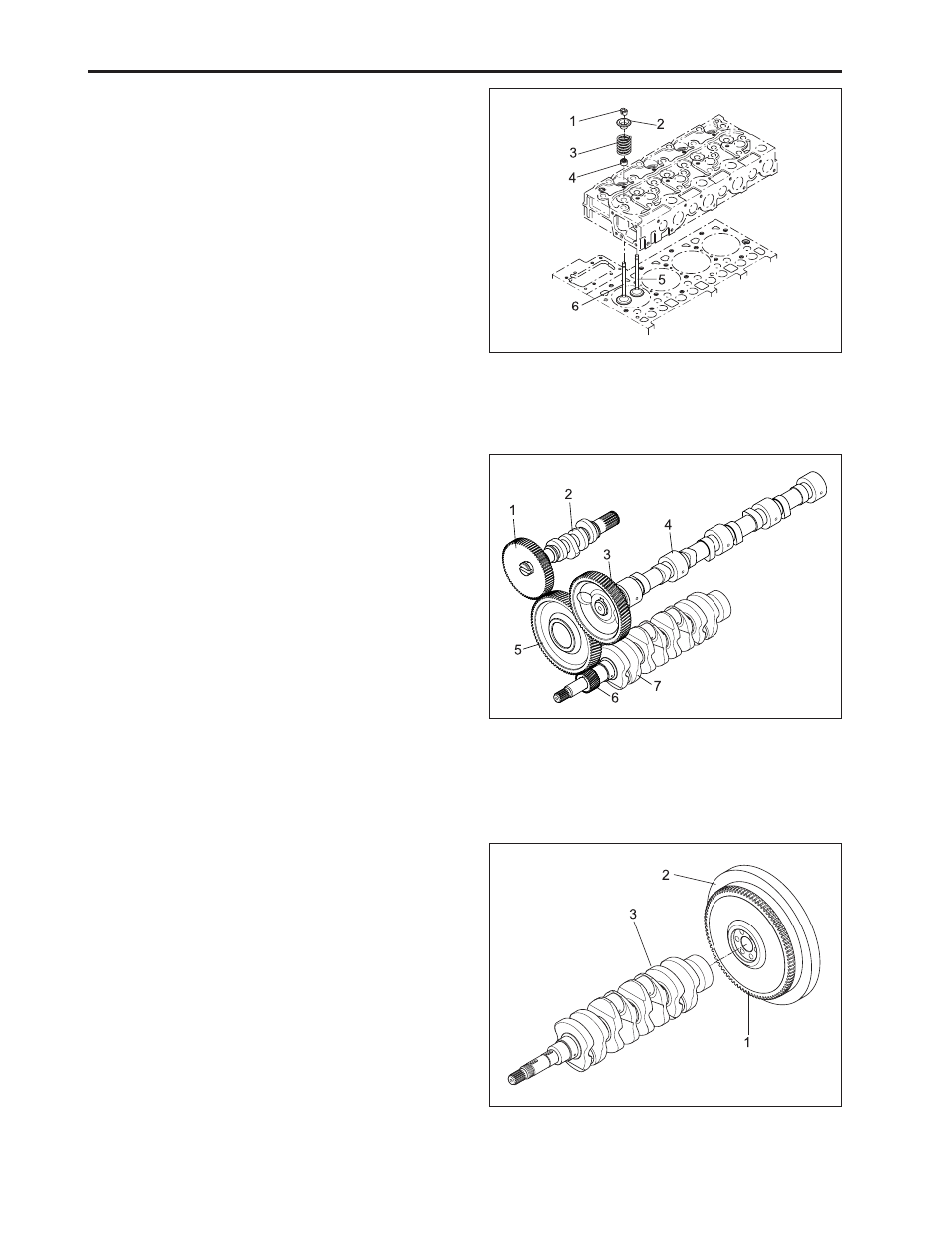
(1) Valve Spring Collet
(4) Valve Stem Seal
(2) Valve Spring Retainer
(5) Exhaust Valve
(3) Valve Spring
(6) Intake Valve
(1) Injection Pump Gear
(5) Idle Gear
(2) Fuel Camshaft
(6) Crankshaft Gear
(3) Camshaft Gear
(7) Crankshaft
(4) Camshaft
(1) Ring Gear
(3) Crankshaft
(2) Flywheel
K. FLYWHEEL
The flywheel is installed on the rear end of the
crankshaft. Its inertia keeps the engine turning at a
constant speed, while the crankshaft tends to speed
up during the power stroke and to slow down during
other stokes. The flywheel has a ring gear (1), which
meshes with the drive pinion of the starter.
The flywheel has marks “TC” and “FI” on its outer rim.
The mark TC shows the piston’s top dead center and
the mark FI shows the fuel injection timing, when they
are aligned with the mark of window on the clutch hous-
ing.
I. INTAKE AND EXHAUST VALVES
The valve and its guide of the intake are different from
those for the exhaust. Other parts, such as the spring,
spring retainers, valve spring collets, valve stem seals
are the same for both the intake and the exhaust. All
contact or sliding surfaces are hardened to increase
wear resistance.
J. TIMING GEARS
The crankshaft drives the oil pump and the idle gear
engaged fuel camshaft and camshaft. The timing for
opening and closing the valves is extremely important
to achieve effective air intake and sufficient gas exhaust.
The appropriate timing can be obtained by aligning the
mark on the crankshaft gear (6) with one the idle gear
(5), idle gear with camshaft gear, idle gear with injec-
tion pump gear, when assembling.