Cub Cadet 8454 User Manual
Page 217
HYDRAULIC SYSTEM
6-23
D569-W02 May-2003
569W626A
569W625A
•
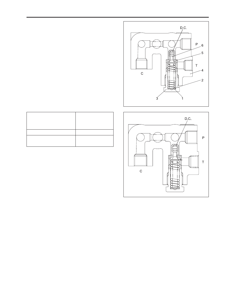
As shown in the figure, a guide is attached at pop-
pet (6) and valve chamber D.C (damping chamber)
located at the bottom of the guide piston. Intake of
valve enable through sliding part of guide and clear-
ance of seat (5) to chamber and minimizes valve
vibration as damping effect of chamber.
•
If oil pressure does not exceed the specified pres-
sure of the relief valve, relief valve will not operate
and oil flows from the hydraulic pump to the inlet of
hydraulic cylinder.
•
As the oil pressure of circuit increases, that of damp-
ing chamber D.C. increases. If pressure exceeds
the specified valve and the spring tension, the valve
will open to flow oil through port T to transmission
case. If oil is discharged sufficiently and its pres-
sure is less than the specified, the valve will be
closed.
Relief valve setting
pressure
Engine speed
Oil temperature
16.2 ~ 17.2 Mpa
16.5 ~ 175 kgf/cm
2
2.347 ~ 2.489 psi
Max.
40 ~ 60 °C
104 ~ 140 °F
e . Relief Valve (Hydraulic Block)
D.C: Damping Chamber
P: Pump Port
C: Cylinder Port
T: Tank Port
(1) Washer
(4) Front Hydraulic B Lock
(2) Shim
(5) Seat
(3) Plug
(6) Poppet