4 hydraulic pressure rise & fall device – Cub Cadet 8454 User Manual
Page 273
HYDRAULIC SYSTEM
6-79
D569-W02 May-2003
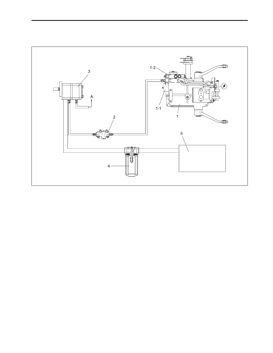
6.4 HYDRAULIC PRESSURE RISE & FALL DEVICE
A. SCHEMATIC DIAGRAM OF HYDRAULIC PRESSURE RISE & FALL DEVICE
(1) Hydraulic Cylinder Ass’y
(1-1) MLS Valve
(1-2) Double Acting Valve
(2) Hydraulic Block
B. PRINCIPLE OF OPERATION
The hydraulic pressure rise & fall device operates hy-
draulic block and hydraulic cylinder assembly by sup-
plying the oil from hydraulic pump 1.
The MLS valve of hydraulic cylinder assembly is avail-
able to work regardless of the load of the machine by
controlling the incoming and outgoing flow rate.
(3) Hydraulic Pump
(4) Hydraulic Filter
(5) Transmission Case
(A) Orbital Unit (Steering Device)
C. DESCRIPTION OF COMPONENTS
1) Hydraulic block: valve to exhaust the front exterior
hydraulic pressure.
2) Double acting valve: valve to exhaust the rear exte-
rior hydraulic pressure.
3) MLS valve: to control hydraulic cylinder assembly
(control of rise and fall of the pressure).
4) Hydraulic cylinder assembly: to control external op-
erating machine with 3 point link.
569W6A9A