Dell PowerEdge C6220 II User Manual
Page 289
Removing and Installing System Components | 289
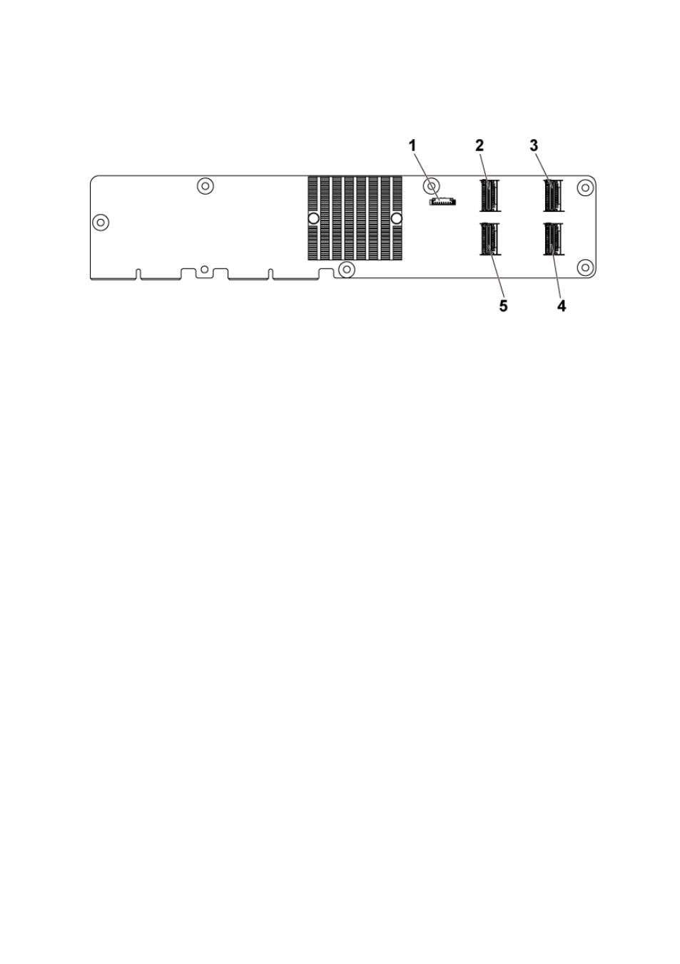
Figure 3-99. Top View of the Expander Card
1
Power control connector
2
mini-SAS connector (4~7)
3
mini-SAS connector (12~15)
4
mini-SAS connector (8~11)
5
mini-SAS connector (0~3)
5 Disconnect front panel cables from the power distribution board. See
Figure 3-108.
Note the routing of the cable on the chassis as you remove them from
the system. You must route these cables properly when you replace
them to prevent the cables from being pinched or crimped.
See also other documents in the category Dell Computer hardware:
- PowerEdge RAID Controller H700 (56 pages)
- PowerEdge RAID Controller H700 (200 pages)
- PowerEdge RAID Controller H700 (178 pages)
- PowerVault TL4000 (2 pages)
- PowerVault TL2000 (176 pages)
- PowerVault TL2000 (16 pages)
- PowerVault TL2000 (3 pages)
- PowerVault TL2000 (116 pages)
- PowerVault 130T DLT (Tape Library) (49 pages)
- PowerVault TL2000 (1 page)
- PowerVault 110T DLT VS80 (Tape Drive) (49 pages)
- PowerVault TL2000 (22 pages)
- PowerVault TL4000 (306 pages)
- PowerVault TL2000 (2 pages)
- PowerEdge 800 (58 pages)
- PowerEdge 800 (87 pages)
- PowerEdge 800 (24 pages)
- PowerEdge 800 (82 pages)
- PowerEdge 800 (2 pages)
- PowerEdge 800 (27 pages)
- PowerEdge 800 (28 pages)
- PowerEdge 6400 (86 pages)
- PowerVault 124T (65 pages)
- PowerVault 124T (4 pages)
- PowerVault 124T (79 pages)
- PowerVault 124T (2 pages)
- PowerVault 124T (64 pages)
- PowerVault 124T (56 pages)
- PowerVault 124T (66 pages)
- PowerVault 124T (57 pages)
- PowerVault 110T LTO (Tape Drive) (28 pages)
- PowerVault 124T (55 pages)
- PowerVault 124T (73 pages)
- PowerVault TL4000 (3 pages)
- PowerVault TL4000 (176 pages)
- PowerVault TL4000 (2 pages)
- PowerVault TL4000 (16 pages)
- PowerVault TL4000 (116 pages)
- PowerVault TL4000 (1 page)
- PowerVault TL4000 (66 pages)
- PowerVault TL4000 (22 pages)
- PowerEdge RAID Controller 6i (156 pages)
- PowerEdge RAID Controller 6i (120 pages)
- PowerVault 715N (Rackmount NAS Appliance) (30 pages)
- PowerVault 715N (Rackmount NAS Appliance) (42 pages)