Dell PowerEdge C6220 II User Manual
Page 251
Removing and Installing System Components | 251
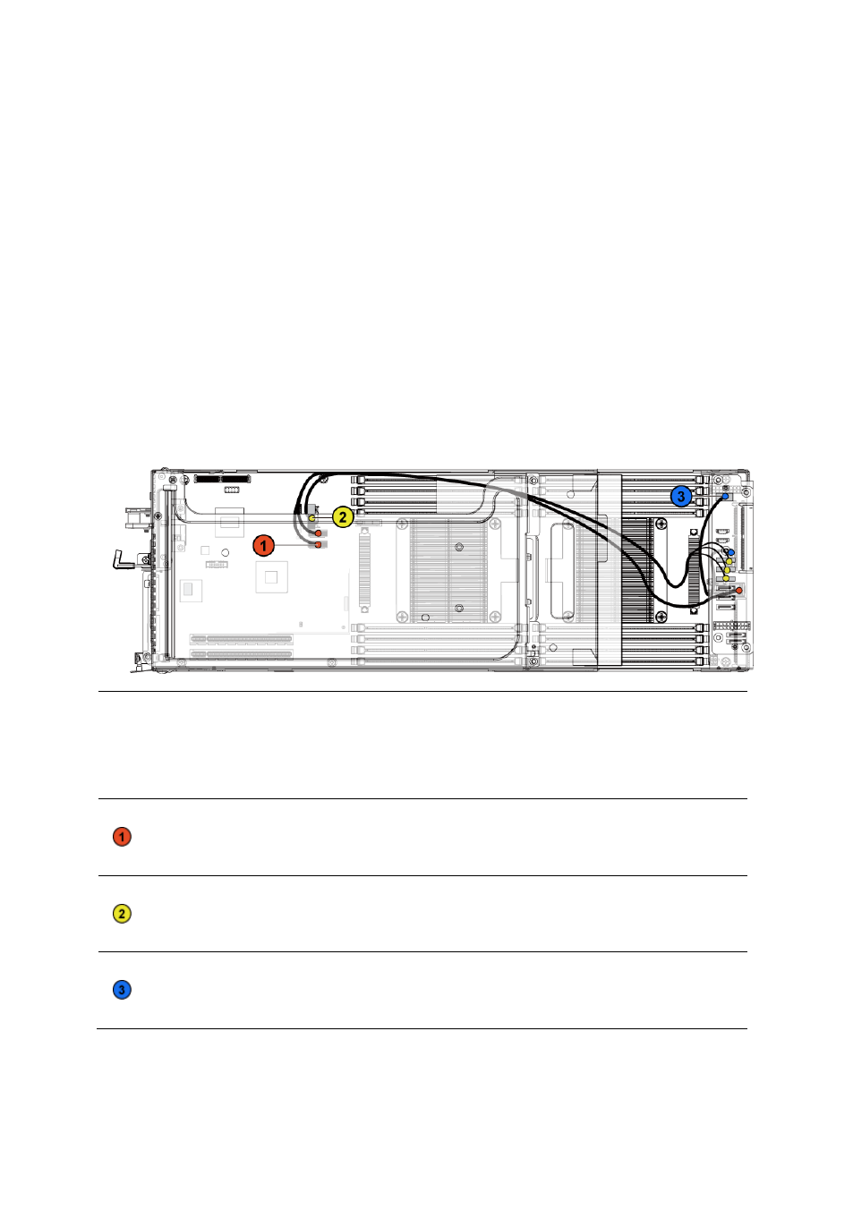
Cable Routing for Onboard SATA Cables (2U Node with 3.5” HDDs)
1 Connect the onboard SATA cable to the system board, and connect
the other end of the cable to the corresponding connectors on the
other side of the system board. See Figure 3-70.
2 Connect the onboard SATA cable to the system board, and connect
the other end of the cable to the corresponding connectors on the
interposer extender for 2U node. See Figure 3-70.
3 Connect the power cable to the system board, and connect the other
end of the cable to the corresponding connector on the interposer
extender for 2U node. See Figure 3-70.
Figure 3-70. Cable Routing for Onboard SATA Cables (2U Node with 3.5” HDDs)
Item
Cable
From
(System Board)
To
(Interposer Extender for
2U Node and System
Board)
Onboard
SATA
cable
Onboard SATA
connectors 4&5
SAS/SATA input
connector 0 on the
system board
Onboard
SATA
cable
Onboard SATA
output connector 0
SATAII connectors
0~2 on the interposer
extender for 2U node
Power cable
Front panel connector Control connector (J3)
on the interposer
extender for 2U node