Operation – Rockwell Automation 1761-HHP-B30 MicroLogix 1000 with Hand-Held Programmer (HHP) User Manual
Page 240
Chapter 13
Using Application Specific Instructions
13–14
Operation
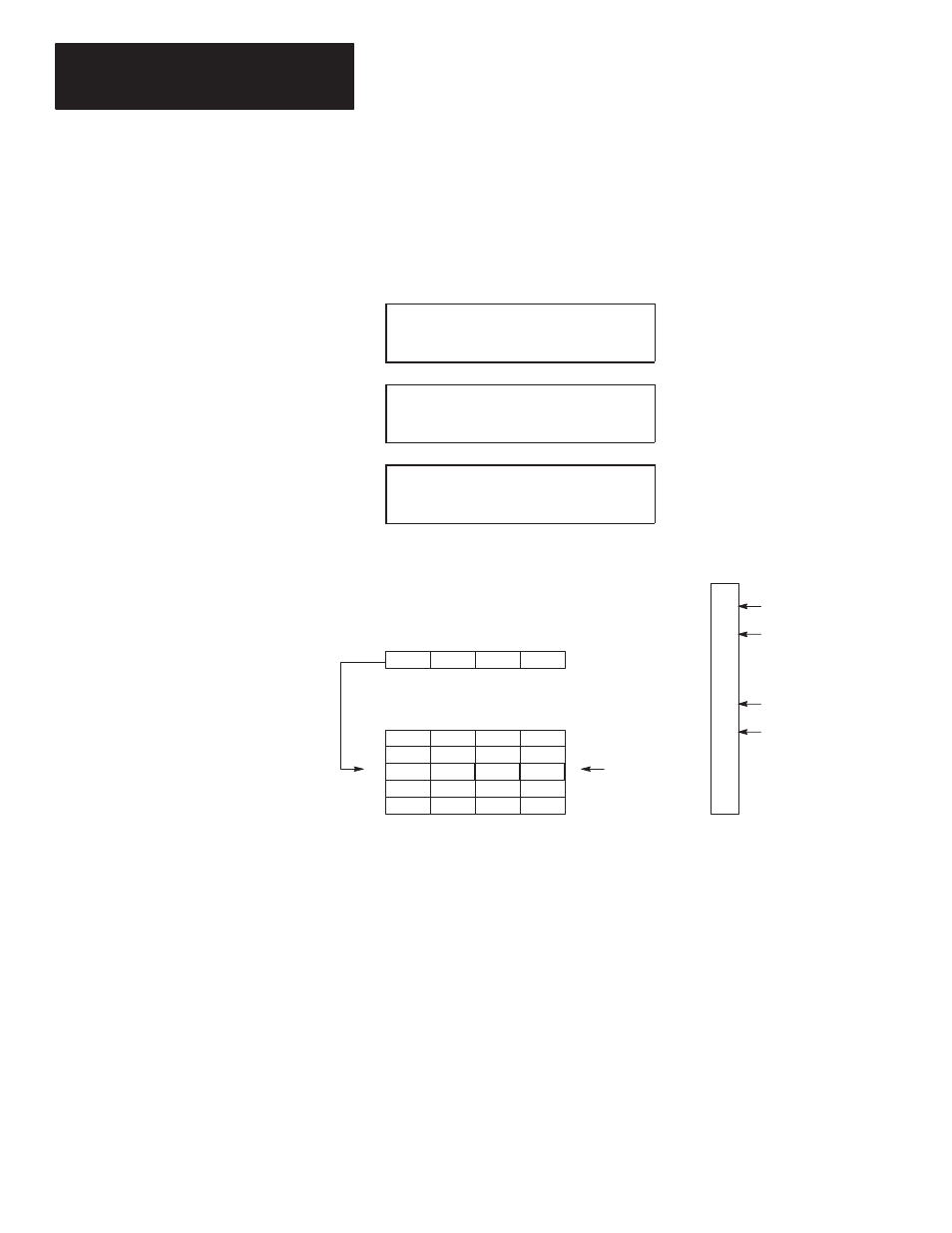
The operation of the SQL instruction is shown in the figure below. The
screens shown above the figure are the condensed screens that appear after
instruction entry is complete. Input word I0 is the source. Data in this word
is loaded into integer file #N30 by the sequencer load instruction.
P 0 1 4
S Q L
F I L E
# N 3 0
0
P 0 1 4
S Q L
S R C
I 0
0 0 0 0 H
P 0 1 4
S Q L
R 0 4
L
4
P
2
0000
0101
0000
1010
0
7
8
15
0000
0000
0000
0000
1010
0010
1111
0101
0000
0101
0000
1010
0000
0000
0000
0000
0000
0000
0000
0000
0
1
2
3
4
Step
N30
31
32
33
34
Word
00
01
02
03
04
05
06
07
08
09
10
11
12
13
14
15
ON
ON
ON
ON
External Inputs
Associated with I0
Source I0
Sequencer Load File #N30
Current Step
When rung conditions change from false-to-true, the SQL enable bit (EN) is
set. The control element R4 increments to the next position in the sequencer
file and loads the contents of source I0 into the corresponding location in the
file. The SQL instruction continues to load the current data into this location
each scan that the rung remains true. When the rung goes false, the enable
bit (EN) is reset.
The instruction loads data into a new file element at each false-to-true
transition of the rung. When step 4 is completed, the done bit (DN) is set.
Operation cycles to position 1 at the next false-to-true transition of the rung
after position 4.
If the source were a file address such as #N40, files #N40 and #N30 would
both have a length of 5 (0–4) and would track through the steps together per
the position value.