Rockwell Automation 1761-HHP-B30 MicroLogix 1000 with Hand-Held Programmer (HHP) User Manual
Page 210
Chapter 11
Using Data Handling Instructions
11–27
P 0 0 0
F F L
S R C
N 1 0
0
P 0 0 0
F F L
F I F O
# N 1 2
0
P 0 0 0
F F L
R 0 0
L
3 4
P
9
P 0 0 0
F F U
F I F O
# N 1 2
0
P 0 0 0
F F U
D E S T
N 1 1
0
P 0 0 0
F F U
R 0 0
L
3 4
P
9
FFL Instruction
When rung conditions change from false-to-true, the controller sets the FFL
enable bit (EN). This loads the contents of the Source, N10, into the stack
structure indicated by the position number, 9. The position value then
increments.
The FFL instruction loads an element at each false-to-true transition of the
rung, until the stack is filled (34 elements). The controller then sets the done
bit (DN), inhibiting further loading.
FFU Instruction
When rung conditions change from false-to-true, the controller sets the FFU
enable bit (EU). This unloads the contents of the element at stack position 0
into the Destination, N11. All data in the stack is shifted one element toward
position zero and the highest numbered element is zeroed. The position
value then decrements.
The FFU instruction unloads an element at each false-to-true transition of the
rung, until the stack is empty. The controller then sets the empty bit (EM).
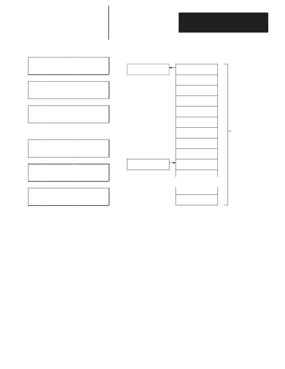
FFU instruction unloads
data from stack #N12 at
position 0, N12.
N12
0
N13
1
N14
2
3
4
5
6
7
8
9
33
34 words are
allocated for FIFO
stack starting at
N12, ending at N45.
FFL–FFU Instruction Pair
Loading and Unloading of Stack #N12
N10
N11
Position
Destination
Source
FFL instruction loads data
into stack #N12 at the next
available position, 9 in this
case.
N45
N15
N16
N17
N18
N19
N20
N21