Optional analog i/o configurations, Optional analog i/o configurations –11, Option board installation/removal – Rockwell Automation 1336Z SPIDER - FRN 2.xxx-5.xxx User Manual
Page 35: Option board setup
Installation/Wiring for Stand-Alone Drives
3–11
Optional Analog I/O
Configurations
Option Board Installation/Removal
The desired analog option boards can be user installed. Prior to
installation, the jumpers at Slot A and/or Slot B must be removed. If a
board is removed at a later time, the jumpers must be reinstalled.
Refer to the detailed instructions supplied with the option boards.
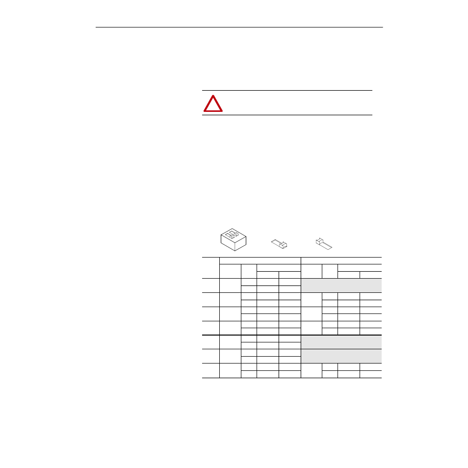
Option Board Setup
Before operation, each installed option board must configured. The
board will have one or two DIP switches depending on the option
selected. The first function (input or output) is configured with the S1
DIP switch – the second function (if present) is configured with S51.
Using the table below, set the switch(es) for correct operation.
Important: Due to different switch manufacturers, the individual
switches will be designated “A or 1” and “B or 2.” In
addition, switch positions will be indicated as “Off or 0”
and “On or 1.”
S1 and S51 Configuration Settings
!
ATTENTION: Drive power must be removed prior to
jumper installation/removal.
Option
DIP Switch S1
DIP Switch S51
Function Mode
Switch Setting
Function Mode
Switch Setting
A/1
B/2
A/1
B/2
LA1
Output 0 10V
Off/“0”
Off/“0”
Configure Standard Analog Input 2 with J11.
See page 3–10 for further information.
20mA On/“1”
On/“1”
LA2
Input 0
10V
Off/“0”
On/“1”
Input 1
10V
Off/“0”
On/“1”
20mA On/“1”
Off/“0”
20mA On/“1”
Off/“0”
LA3
Output 0 10V
Off/“0”
Off/“0”
Output 1 10V
Off/“0”
Off/“0”
20mA On/“1”
On/“1”
20mA On/“1”
On/“1”
LA4
Input 2
10V
Off/“0”
On/“1”
Output 1 10V
Off/“0”
Off/“0”
20mA On/“1”
Off/“0”
20mA On/“1”
On/“1”
LA5
Output 0 10V
Off/“0”
Off/“0”
20mA On/“1”
On/“1”
LA6
Input 0
10V
Off/“0”
On/“1”
20mA On/“1”
Off/“0”
LA7
Input 0
10V
Off/“0”
On/“1”
Input 1
10V
Off/“0”
On/“1”
20mA On/“1”
Off/“0”
20mA On/“1”
Off/“0”
1
2
On / 1 =
Off / 0 =
Switches S1 and S51