Power cabling, Power cabling –9, General installation for all drives 2–9 – Rockwell Automation 1336Z SPIDER - FRN 2.xxx-5.xxx User Manual
Page 19
General Installation for All Drives
2–9
Power Cabling
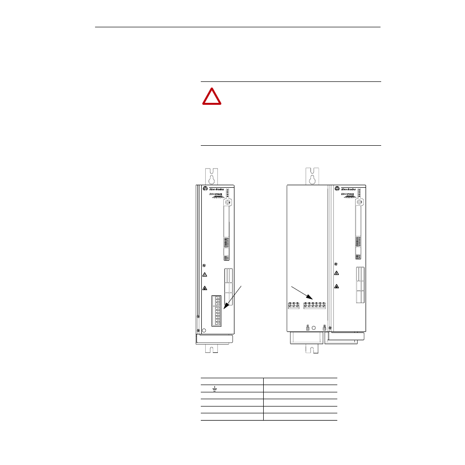
Input and output power connections are performed through the power
terminal blocks (see Figure 2.1 for location).
Important: For maintenance and setup procedures, the drive may be
operated without a motor connected.
Figure 2.1
Power Terminal Block Locations
Table 2.C
Power Terminal Block Signals
!
ATTENTION: The National Codes and standards (NEC,
VDE, BSI etc.) and local codes outline provisions for safely
installing electrical equipment. Installation must comply
with specifications regarding wire types, conductor sizes,
branch circuit protection and disconnect devices. Failure to
do so may result in personal injury and/or equipment dam-
age.
PWR
RUN
STOP
FAULT
TB1
TB2
TB3
TB4
TB5
TB6
TB7
DEVICE IS LIVE UP TO
180SEC AFTER REMOVING
MAINS VOLTAGE.
GERÄT FÜHRT BIS
180SEK NACH DEM
AUSSCHALTEN SPANNUNG.
L'APPAREIL RESTE SOUS
TENSION JUSQU'A 180 S
APRES LA MISE HORS SERVICE.
PE
L1
L2
L3
45 (–)
47 (+)
48
U
V
W
PWR
RUN
STOP
FAULT
TB1
TB2
TB3
TB4
TB5
TB6
TB7
DEVICE IS LIVE UP TO
180SEC AFTER REMOVING
MAINS VOLTAGE.
GERÄT FÜHRT BIS
180SEK NACH DEM
AUSSCHALTEN SPANNUNG.
L'APPAREIL RESTE SOUS
TENSION JUSQU'A 180 S
APRES LA MISE HORS SERVICE.
PE
M4
L1
L2
L3
45
(–)
47
(+)
48
U
V
W
M4
Power Terminal Blocks
Cover Removed to
Show Terminal
Blocks
Terminal
Description
PE
Potential Earth Ground
L1 (R), L2 (S), L3 (T)
AC Line Input Terminals
(+) 47 & (–) 45
DC Bus Terminals
(+) 47 & 48
Braking Resistor
U (T1), V (T2), W (T3)
Motor Connection