Chapter 3, Installation/wiring for stand-alone drives, Control and signal wiring – Rockwell Automation 1336Z SPIDER - FRN 2.xxx-5.xxx User Manual
Page 25: Installation/wiring for stand- alone drives, Control and signal wiring –1, Chapter
Chapter
3
Installation/Wiring for Stand-Alone
Drives
Chapter 3 provides the information you need to perform the control
and signal wiring for Stand-alone 1336 SPIDER Drives. In addition,
installation information is provided for the Analog Option Boards.
Refer to Chapter 2 for general installation and wiring.
Control and Signal Wiring
General Wiring Information
General requirements for analog and digital signal wire include:
stranded copper 0.750-0.283 mm
2
(18-22 AWG), twisted-pair, 100%
shield, 300V minimum insulation rating and a temperature rating
suitable for the application (not less than 60 degrees C.). Refer to
Table 3.A for terminal block specifications and Figure 3.1 for
locations.
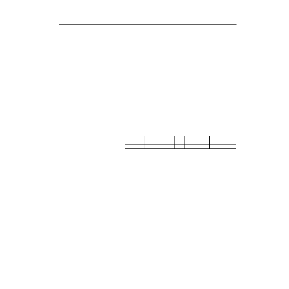
Table 3.A
Control and Signal Terminal Block Specifications
1
Wire sizes given are maximum/minimum sizes that terminal block will accept - these are not
recommendations. Use Copper wire only. Wire gauge requirements and recommendations are based
on 75 degree C. Do not reduce wire gauge when using higher temperature wire.
Signal Connections
If the drive control connections are to be linked to an electronic
circuit or device, the common or 0V line should, if possible, be
grounded at the device (source) end only.
Important: The signal common (0V) of the drive is internally
connected to PE. User speed reference signals are
terminated to logic common at TB2, terminal 5. This puts
the negative (or common) side of these signals at earth
ground potential. Control schemes must be examined for
possible conflicts with this type of grounding scheme.
Cable Routing
If unshielded cable is used, signal circuits should not run parallel to
motor cables or unfiltered supply cables with a spacing less than 0.3
meters (1 foot). Cable tray metal dividers or separate conduit should
be used.
Important: When user installed control and signal wiring with an
insulation rating of less than 600V is used, this wiring must
be routed inside the drive enclosure and separated from
any other wiring and/or uninsulated live parts.
Drive Catalog
Number
Max./Min. Wire Size
1
mm2 (AWG)
Screw
Size
Torque Range
N-m (lb.-in.)
Remove Insulation
mm (in.)
All
0.14-1.5 (28-16)
M2
0.22-0.25 (1.9-2.2) 9 (0.35)