Pulse input/output option, Digital outputs, Pulse input/output option –8 digital outputs –8 – Rockwell Automation 1336Z SPIDER - FRN 2.xxx-5.xxx User Manual
Page 32
3–8
Installation/Wiring for Stand-Alone Drives
Pulse Input/Output Option
Pulse Input
The pulse input signal must be an externally powered square-wave
pulse at a 5V TTL logic level. As measured at the terminal block,
circuits in the high state must generate a voltage between 3.6 and
5.5V DC at 8 mA. Circuits in the low state must generate a voltage
between 0.0 and 0.8V DC. Maximum input frequency is 250kHz.
Scale factor [Pulse/Enc Scale] must be set.
Pulse Output
Provides a TTL pulse train suitable for driving up to three
1336 SPIDER pulse inputs or a separate 125 ohm load at TTL levels
(4V at 32 mA source, 0.8V at 3.2 mA sink).
Important: An LA5 Analog Option must be installed to use the pulse
input/output options. See Figure 3.4 for terminal
designations.
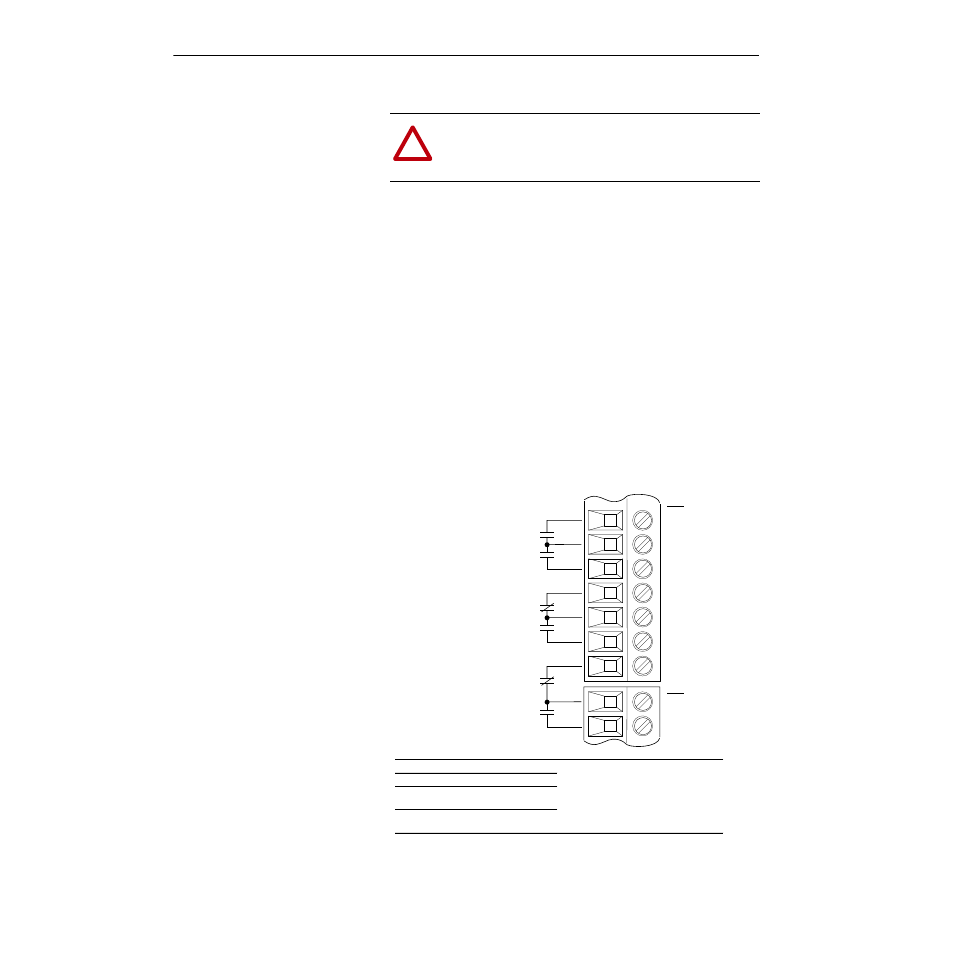
Digital Outputs
The digital outputs are at terminals 10 through 18 of TB3-TB4.
Figure 3.3
Digital Outputs
!
ATTENTION: If input voltages are maintained at levels
above
±
15V DC, signals may be degraded and component
damage may result.
CR2
CR1
CR3
CR3
CR4
CR4
Terminal
10, 11
11, 12
13, 14
14, 15
16, 17
17, 18
Signal
CR1 Programmable Contact
CR2 Programmable Contact
CR3 Programmable Contact
CR4 Programmable Contact
Resistive Rating = 115V AC/30V DC, 5.0A
Inductive Rating = 115V AC/30V DC, 2.0A
Contacts Shown
in Unpowered State
(or powered state with
fault/alarm present)
Important: The power supply used for relay contact outputs requires a field installation
of transient voltage surge suppression with maximum clamping voltage of
2.5 kV on all control boards.
10
11
12
13
14
15
Output 1
Common
Output 2
Output 3
Common
Output 4
17
TB4
18
Common
Output 6
16
Output 5
TB3