Pi max error, Pulse out select, Pulse out scale – Rockwell Automation 1336Z SPIDER - FRN 2.xxx-5.xxx User Manual
Page 101: Pulse in scale, At time, Remote cr output
Programming
7–29
[PI Max Error]
This parameter is used with the process PI loop and sets
the PI error value which activates CR1-4 (if selected).The
relay(s) will be activated when [PI Error] exceeds this
value.
Parameter Number
293
Parameter Type
Read Only
Display Units / Drive Units
0.01 Hertz / 32767 = Maximum Freq Forward
Factory Default
Maximum Freq Forward
Minimum Value
–400.00 Hz
Maximum Value
400.00 Hz
[Pulse Out Select]
– Stand-Alone Version Only
This parameter selects the source value that drives pulse
output.
Parameter Number
280
Parameter Type
Read and Write
Factory Default
“Output Freq”
Units
Display Drive Range
“Output Freq” 0
See [Output Freq]
“Encoder Freq” 1
See [Encoder Freq]
“Acc/Dec Freq” 2
See Note
Note: Output frequency command of the drive directly at the output of the accel/decel ramp gen-
erator. It does not include any modification due to selected speed regulation mode via [Speed
Control].
[Pulse Out Scale]
– Stand-Alone Version Only
Provides a scaling factor for pulse output.
Pulse Output Rate = Hz x [Pulse Out Scale]
The pulse output will not provide a rate lower than 21 Hz.
A command less than 21 Hz will generate 0 Hz output. To
provide smooth operation across a wide speed range,
select the maximum scale factor possible.
Parameter Number
281
Parameter Type
Read and Write
Display Units / Drive Units
Factor / Factor
Factory Default
1
Minimum Value
1
Maximum Value
64
Example:
[Pulse Out Select] is set to “Output Freq” and drive is programmed for [Maximum Freq] = 60 Hz.
When the drive output is 60 Hz, the Pulse Output Rate is adjustable from 60 Hz (60 x 1) to 3840
Hz (60 x 64).
[Pulse In Scale]
– Stand-Alone Version Only
Provides a scaling factor for the pulse input.
Parameter Number
264
Parameter Type
Read and Write
Display Units / Drive Units
Factor / Pulses per Rev
Factory Default
64 PPR
Minimum Value
1
Maximum Value
4096
Example:
4 Pole Motor, 60 Hz = Max. Speed.
The 1336-MOD-N1 option outputs 64 Hz/Hz. At full analog reference, the pulse input to the drive
will be 60 Hz x 64 Hz/Hz = 3840 pulses/sec.
[At Time]
Sets the delay time for the activation of the CR1-4 relays.
The relay is activated at Start + [At Time] seconds. This
delay affects all relays.
Parameter Number
327
Parameter Type
Read and Write
Display Units / Units
0.01 Second / Seconds x 100
Factory Default
0.00 Sec
Minimum Value
0.00 Sec
Maximum Value
360.00 Sec
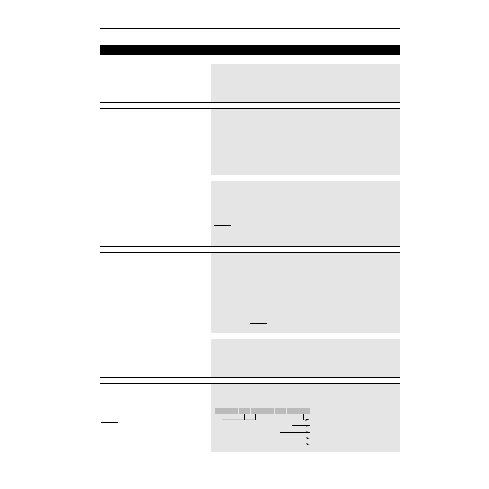
[Remote CR Output]
Individual bits control relay outputs when selected with
[CR1-4 Out Select]. 1 = Energize Coil. This parameter is
reset to the default on power-up.
Example:
If [CR2 Out Select] is set to “Remote,” bit 1 of this parameter
will control CR2.
A Status description (bit ENUM) is displayed on line 1
(except Series A HIMs below version 3.0).
Parameter Number
326
Parameter Type
Read and Write
Factory Default
xxxx0000
Scale
Factor
Incoming Pulse Rate (Hz)
Desired Command Freq.
=
Scale Factor =
3840 Hz
60 Hz
= 64
Bit 7 Bit 6 Bit 5 Bit 4 Bit 3 Bit 2 Bit 1 Bit 0
CR1 Output
CR2 Output
CR3 Output
CR4 Output
Not Used