Rockwell Automation 1336Z SPIDER - FRN 2.xxx-5.xxx User Manual
Page 18
2–8
General Installation for All Drives
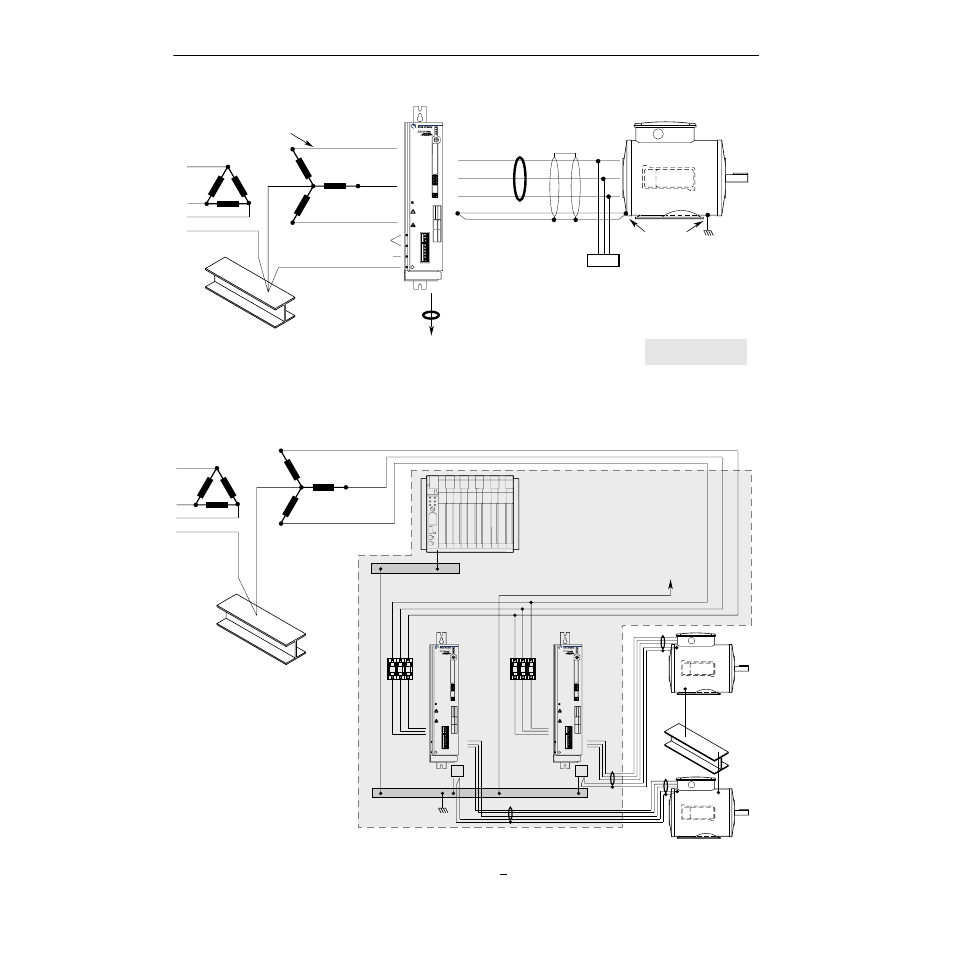
General Grounding
Single-Point Grounding/Panel Layout
Important: Grounding requirements will vary with the drives being used. Other drives with True Earth (TE) terminals must have a zero potential bus, separate from potential
earth (PE) ground bus. Note that buses can be tied together at one point in the control cabinet or brought back separately to the building ground grid (tied within 3 meters
(10 feet)).
L1 (R)
L2 (S)
L3 (T)
PE
to Motor & Signal PE Ground
Do Not Use
U (T1)
Shield
RIO/DH+
or Analog
Shield*
Common
Mode
Core*
Common
Mode Core*
Conduit/4-Wire Cable
To Computer/Position Controller
(for further grounding info, see "
Control and Signal Wiring" in Chapter 3 or 4
)
Ground per
Local Codes
Motor Frame
Motor
Terminator*
PE
V (T2)
W (T3)
PE/Gnd.
* Options that can be
installed as needed.
Nearest
Building Structure Steel
PWR
RUN
STOP
FAULT
TB1
TB2
TB3
TB4
TB5
TB6
TB7
DEVICE IS LIVE UP TO
180SEC AFTER REMOVING
MAINS VOLTAGE.
GERÄT FÜHRT BIS
180SEK NACH DEM
AUSSCHALTEN SPANNUNG.
L'APPAREIL RESTE SOUS
TENSION JUSQU'A 180 S
APRES LA MISE HORS SERVICE.
PE
L1 (R)
L2 (S)
Nearest
Building Structure Steel
To Nearest Building
Structure Steel
Nearest Building
Structure Steel
1336 SPIDER
1336 SPIDER
L3 (T)
PE
PE
Zero Volt Potential Bus
(Isolated from Panel)
PE Ground Bus
(Grounded to Panel)
For Programmable Controller
grounding recommendations,
refer to publication 1770-4.1
PWR
RUN
STOP
FAULT
TB1
TB2
TB3
TB4
TB5
TB6
TB7
DEVICE IS LIVE UP TO
180SEC AFTER REMOVING
MAINS VOLTAGE.
GERÄT FÜHRT BIS
180SEK NACH DEM
AUSSCHALTEN SPANNUNG.
L'APPAREIL RESTE SOUS
TENSION JUSQU'A 180 S
APRES LA MISE HORS SERVICE.
PE
PWR
RUN
STOP
FAULT
TB1
TB2
TB3
TB4
TB5
TB6
TB7
DEVICE IS LIVE UP TO
180SEC AFTER REMOVING
MAINS VOLTAGE.
GERÄT FÜHRT BIS
180SEK NACH DEM
AUSSCHALTEN SPANNUNG.
L'APPAREIL RESTE SOUS
TENSION JUSQU'A 180 S
APRES LA MISE HORS SERVICE.
PE