Rockwell Automation 284E ArmorStart with EtherNet/IP - User Manual User Manual
Page 42
42
Rockwell Automation Publication 280E-UM001B-EN-P - July 2012
Chapter 2 Installation and Wiring
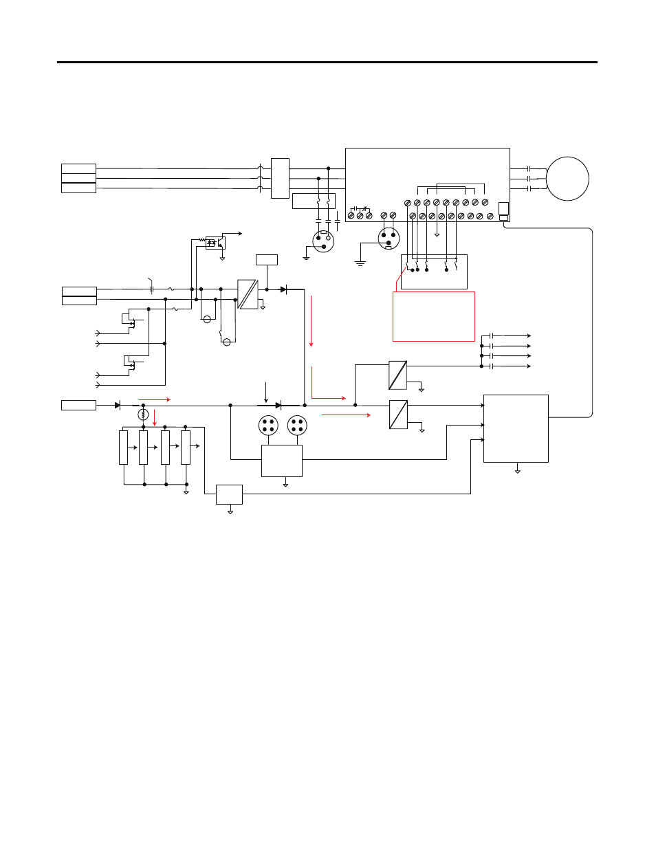
Figure 19 - ArmorStart Ethernet Bulletin 284E Drive Diagram
Input 0
Input 1
Input 2
Input 3
4 Inputs
50mA Max/input depends
on sensor attached to input
26V
24V DC
Fan
24V DC
11 -
25V DC
+24V DC Status
5V DC
11 -
25V DC
+5V DC
AS Logic
Circuits
140M Trip
140M Status
Brake CNTR Status
Output CNTR Status
1
Input 10mA @ 24V DC
Input 10mA @ 24V DC
Input 10mA @ 24V DC
Input 10mA @ 24V DC
Current supplied by
control power due to the
power supply voltage
being greater than A3
voltage
Reversed bias
under normal
operation
Current supplied by
A3 when A1 control
power is lost
Sensorless Vector Control
Filt
er
O
ption
140M
Off/Tripped
On
7A
Class CC
2.5A
Class CC
AS Logic
Control
Power
Sense
Output
Contactor
O
PTC
Short
Detect
Motor
Source Brake
Option
B
PF40
R1
R2
L1
L2
L3
T1
T2
T3
R1
R2
R3
01
02
04
05
06
07
08
09
11
12
13
14
15
16
17
18
19
03
BR+ BR-
Dynamic Brake
Connector
Option
RJ-45
300mA Max
Note: This switch is controlled
by the Control Power Logic
sense. If control power is
present, switch is closed.
Prevents drive from running
when there is no power for the
fan
1 - Output CNTR Status not
available when SM option specified
Output Contactor
Option
Source Brake
Option
3A
Class CC
A3
Ethernet
Logic
A1
A2
Output A
Output B
1 Ampere
Total
L1
L2
L3
2A SC Protected
2A SC Protected
Port 2
Port 1
140M