Control module led status and reset, Table 34, Table 33 – Rockwell Automation 284E ArmorStart with EtherNet/IP - User Manual User Manual
Page 212
212
Rockwell Automation Publication 280E-UM001B-EN-P - July 2012
Chapter 9 Diagnostics
Control Module LED
Status and Reset
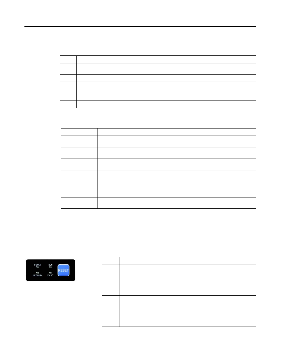
The Control Module LED status and diagnostics consists of four status LEDs
and a Reset button. The following is a brief explanation of the operation of each
LED found on the Control Module.
The “Reset Button” is a local trip reset.
Table 33 - “Steady Red” MOD LED Status (Refer to Table 32.)
Fault Type
Description
0
EEPROM Fault
Non-volatile memory value out of range for a local parameter, or a write failure detected. This fault is also reflected by
a solid red MOD status LED.
1
Internal Comm2
The Internal communication connection has timed out. This fault is also reflected by a flashing red MOD status LED.
2
Hardware Fault
Internal diagnostics checks failed. This fault is also reflected by a solid red MOD status LED.
3
Control Module
An illegal or unsupported Control Module product code or revision has been detected. Also reported if no Control
Module is detected on power up. This fault is also reflected by a solid red MOD status LED.
4…15
Reserved
Reserved
Table 34 - Network Status Indicator
Indicator State
Summary
Requirement
Steady OFF
Not powered, no IP address
If the device does not have an IP address (or is powered OFF), the network status
indicator shall be steady OFF.
Flashing Green
No connections
If the device has no established connections, but has obtained an IP address, the
network status indicator shall be flashing green.
Steady Green
Connected
If the device has at least one established connection (even to the Message Router),
the network status indicator shall be steady green.
Flashing Red
Connection timeout
If one or more of the connections in which this device is the target has timed out,
the network status indicator shall be flashing red. This shall be left if only all timed
out connections are reestablished or if the device is reset.
Steady Red
Duplicate IP
If the device has detected that the IP addtress is already in use, the network status
indicator shal be steady red.
Flashing Red/Green
Self-test
While the device is performing its power up testing, the network status indicator
shall be flashing green/red.
Figure 81 - LED Status
Indication and Reset
Table 35 - Control Module LED Status Indication
LED
Definition
Recommended Action
Power
This LED will be illuminated solid green when
switched control power is present and with the
proper polarity.
Ensure 24V DC is present on A1 and A2. Check if the
local disconnect is in the OFF position.
Run
This LED will be illuminated solid green when a
start command and control power is present.
Ensure 24V DC is present on A1 and A3. Check if the
user is properly commanding to RUN via Instance
162 or 166.
Network
This bicolor LED is used to indicate the status of the
internal network connection.
See Table 34, Network Status Indicator table above
for additional information.
Fault
This LED is used to indicate the fault status of the
ArmorStart. When the unit is faulted, the unit will
respond with a specific blink pattern to identify the
fault.
See Table 36 and Table 37 below for additional
information.