Control module fault led indications, See table 36 and – Rockwell Automation 284E ArmorStart with EtherNet/IP - User Manual User Manual
Page 213
Rockwell Automation Publication 280E-UM001B-EN-P - July 2012
213
Diagnostics Chapter 9
Control Module Fault
LED Indications
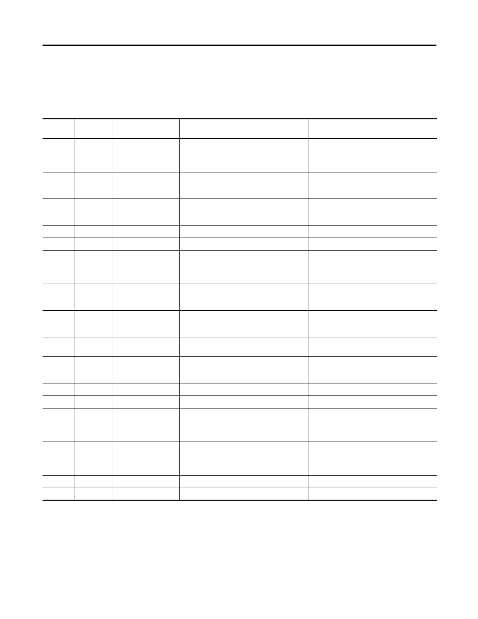
Table 36 - Fault LED Indicators for Bulletin 280E/281E
Blink
Pattern
Auto-
Resettable
Bulletin 280E/281E Trip
Status
Description
Action
1
No
Short Circuit
The circuit breaker (140M) has tripped.
Determine cause of trip. Try to reset the circuit breaker
using the disconnect handle. If the conditions continue,
check power wiring or replace based module. This cannot
be disabled.
2
Yes
Overload
The load has drawn excessive current and based on the
trip class selected, the device has tripped.
Verify that the load is operating correctly and the
ArmorStart is properly set-up. the fault cannot be
disabled.
3
Yes
Phase Loss
The ArmorStart has detected a missing phase.
Verify that 3-phase voltage is present at the line side
connections. This fault can be disabled and is disabled by
default.
4
—
Reserved
Not Used
—
5
—
Reserved
Not Used
—
6
Yes
Control Pwr Loss (Switched
Power)
The ArmorStart has detected a loss of the control power
voltage.
Check control voltage, wiring, and proper polarity (A1/A2
terminal). Also, check and replace the control voltage
fuse, if necessary. This fault can be disabled and is
disabled by default.
7
Yes
Input Fault
This error indicates a shorted sensor, shorted input
device, wiring input mistakes, or a blown output fuse.
Correct, isolated or remove wiring error prior to
restarting the system. This fault can be disabled and is
disabled by default.
8
Yes
Over Temperature
This fault is generated when the operating temperature
has been exceeded. This fault cannot be disabled.
Check for blocked or dirty heat sink fins. Verify that
ambient temperature has not exceeded 40 °C (104 °F). 1.
Clear the fault or cycle power to the drive.
9
Yes
Phase Imbalance
The ArmorStart has detected a voltage imbalance.
Check the power system and correct if necessary. This
fault can be disabled and is disabled by default.
10
Yes
Control Power (24V DC) Lost
(Unswitched Power)
The 24V DC power supply is below tolerance threshold.
Check the state of the network power supply (A3/A1
terminal) and look for media problems. This fault can be
disabled and is disabled by default.
11
—
Reserved
Not Used
—
12
—
Reserved
Not Used
—
13
No
EEprom
This is a major fault, which renders the ArmorStart
inoperable. Possible causes of this fault are transients
induced during EEprom storage routines.
If the fault was initiated by a transient, power cycling
should clear the problem, otherwise replacement of the
ArmorStart may be required. This fault cannot be
disabled.
14
No
Hdw Flt
This fault indicates that a serious hardware problem
exists.
Check for a base/starter module mismatch. If no
mismatch exists, the ArmorStart may need to be
replaced. (Hdw Flt is the factory-enabled default
setting.) This fault cannot be disabled.
15
—
Reserved
Not Used
—
16
—
Reserved
Not Used
—