Dynamic braking resistors – Rockwell Automation 284E ArmorStart with EtherNet/IP - User Manual User Manual
Page 259
Rockwell Automation Publication 280E-UM001B-EN-P - July 2012
259
Accessories Chapter 12
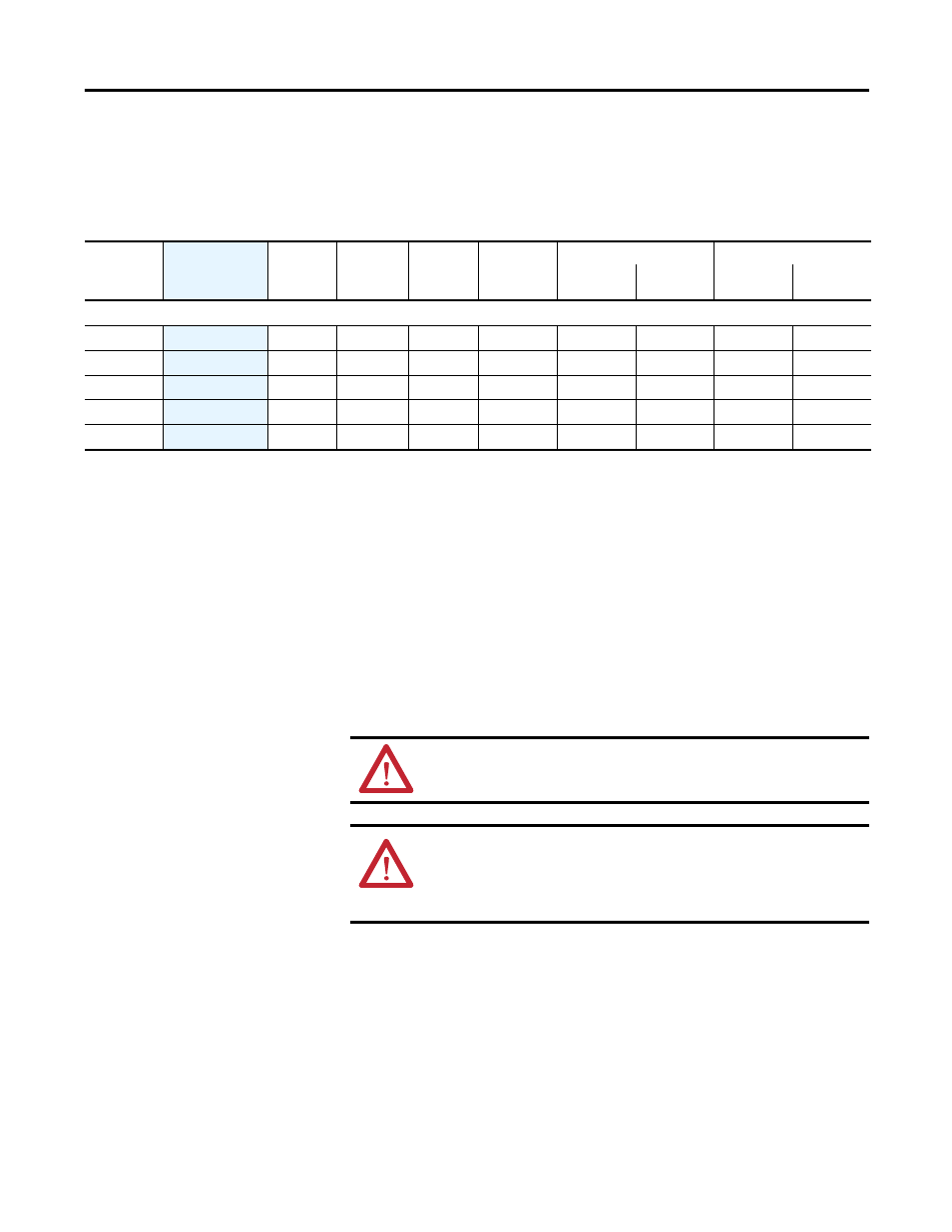
Dynamic Braking Resistors
Sensorless Vector Control (SVC) Minimum Resistance and
Recommended Modules for Option DB
Note 1:
Always check resistor ohmic value against minimum resistance for drive
being used.
Note 2:
Duty cycle listed is based on full speed to zero speed deceleration.
For constant regen at full speed, duty cycle capability is half of what is listed.
Application Type 1 represents maximum capability up to 100% braking torque
where possible.
Application Type 2 represents more than 100% braking torque where possible, up
to a maximum of 150%.
Note 3:
Dynamic brake modules have an IP20 rating.
Table 47 - Dynamic Brake Specification for Option DB (IP20 Resistor)
Drive and
Motor Size kW
(Hp)
Cat. No. ➊
Resistance
Ohms ±5%
Continuous
Power kW
Max Energy
kJ
Max Braking
Torque % of
Motor
Application Type 1
Application Type 2
Braking Torque
% of Motor
Duty Cycle %
Braking Torque
% of Motor
Duty Cycle %
380…480 Volt AC Input Drives
0.37 (0.5)
AK-R2-360P500
360 0.086 17 305% 100% 47% 150% 31%
0.75 (1)
AK-R2-360P500
360 0.086 17 220% 100% 23% 150% 15%
1.5 (2)
AK-R2-360P500
360 0.086 17 110% 100% 12% 110% 11%
2.2 (3)
AK-R2-120P1K2
120 0.26 52 197% 100% 24% 150% 16%
4 (5)
AK-R2-120P1K2
120 0.26 52 124% 100% 13% 124% 10%
ATTENTION: Resistor temperature may exceed 200°C.
ATTENTION: AC drives do not offer protection for externally mounted brake resistors,
especially in the case of brake IGBT failure. A risk of fire exists if external braking
resistors are not protected. External resistor packages must be protected from over
temperature or the protective circuit shown, or equivalent, must be supplied.