Table 2, Table 3, Table 4 – Rockwell Automation 20-COMM-ER 20-COMM-ER Dual-Port EtherNet/IP Communication Adapter User Manual User Manual
Page 64
64
Rockwell Automation Publication 20COMM-UM015B-EN-P - July 2013
Chapter 4 Configuring the I/O
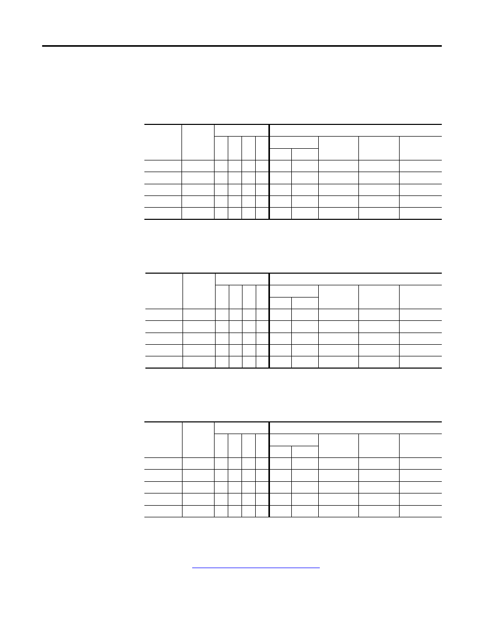
Table 2 - Devices with 16-bit Reference/Feedback and 16-bit Datalinks
These products include the following:
Table 3 - Devices with 16-bit Reference/Feedback and 32-bit Datalinks
These products include the following:
Table 4 - Drives with 32-bit Reference/Feedback and 32-bit Datalinks
These products include the following:
·
PowerFlex 70 drives with standard or enhanced control
·
SMC Flex smart motor controllers
·
PowerFlex 700 drives with standard control
·
SMC-50 smart motor controllers
·
PowerFlex 700H drives
Logic
Command/
Status
Ref/Fdbk
(16-bit)
Datalinks (16-bit) User Configured Settings
A
B
C
D
Size in Words
Par. 23 -
[DPI I/O Cfg]
Par. 35 -
[M-S Input]
Par. 36 -
[M-S Output]
Input Output
✔
✔
4
2
…0 0001
…0 0001
…0 0001
✔
✔
✔
6
4
…0 0011
…0 0011
…0 0011
✔
✔
✔
✔
8
6
…0 0111
…0 0111
…0 0111
✔
✔
✔
✔
✔
10
8
…0 1111
…0 1111
…0 1111
✔
✔
✔
✔
✔
✔
12
10
…1 1111
…1 1111
…1 1111
·
PowerFlex 700 drives with vector control
·
PowerFlex Digital DC drives
·
PowerFlex 700L drives with 700 control
·
SMC Controllers
Logic
Command/
Status
Ref/Fdbk
(16-bit)
Datalinks (32-bit) User Configured Settings
A
B C
D
Size in Words
Par. 23 -
[DPI I/O Cfg]
Par. 35 -
[M-S Input]
Par. 36 -
[M-S Output]
Input Output
✔
✔
4
2
…0 0001
…0 0001
…0 0001
✔
✔
✔
8
6
…0 0011
…0 0011
…0 0011
✔
✔
✔
✔
12
10
…0 0111
…0 0111
…0 0111
✔
✔
✔
✔
✔
16
14
…0 1111
…0 1111
…0 1111
✔
✔
✔
✔
✔
✔
20
18
…1 1111
…1 1111
…1 1111
·
PowerFlex 700S drives with Phase I or Phase II control
·
PowerFlex 753 drives
·
PowerFlex 700L drives with 700S control
·
PowerFlex 755 drives
Logic
Command/
Status
Ref/Fdbk
(32-bit)
Datalinks (32-bit) User Configured Settings
A
B
C
D
Size in Words
Par. 23 -
[DPI I/O Cfg]
Par. 35 -
[M-S Input]
Par. 36 -
[M-S Output]
Input Output
✔
✔
6
4
…0 0001
…0 0001
…0 0001
✔
✔
✔
10
8
…0 0011
…0 0011
…0 0011
✔
✔
✔
✔
14
12
…0 0111
…0 0111
…0 0111
✔
✔
✔
✔
✔
18
16
…0 1111
…0 1111
…0 1111
✔
✔
✔
✔
✔
✔
22
20
…1 1111
…1 1111
…1 1111
TIP
For instructions on configuring the I/O for the adapter using Parameter 25 -
[DPI I/O Cfg] and its Master-Slave Hierarchy using Parameters 37 - [M-S
Input] and 38 - [M-S Output], see
Setting the I/O Configuration on page 35
.