Rockwell Automation 20-COMM-ER 20-COMM-ER Dual-Port EtherNet/IP Communication Adapter User Manual User Manual
Page 56
56
Rockwell Automation Publication 20COMM-UM015B-EN-P - July 2013
Chapter 4 Configuring the I/O
10.
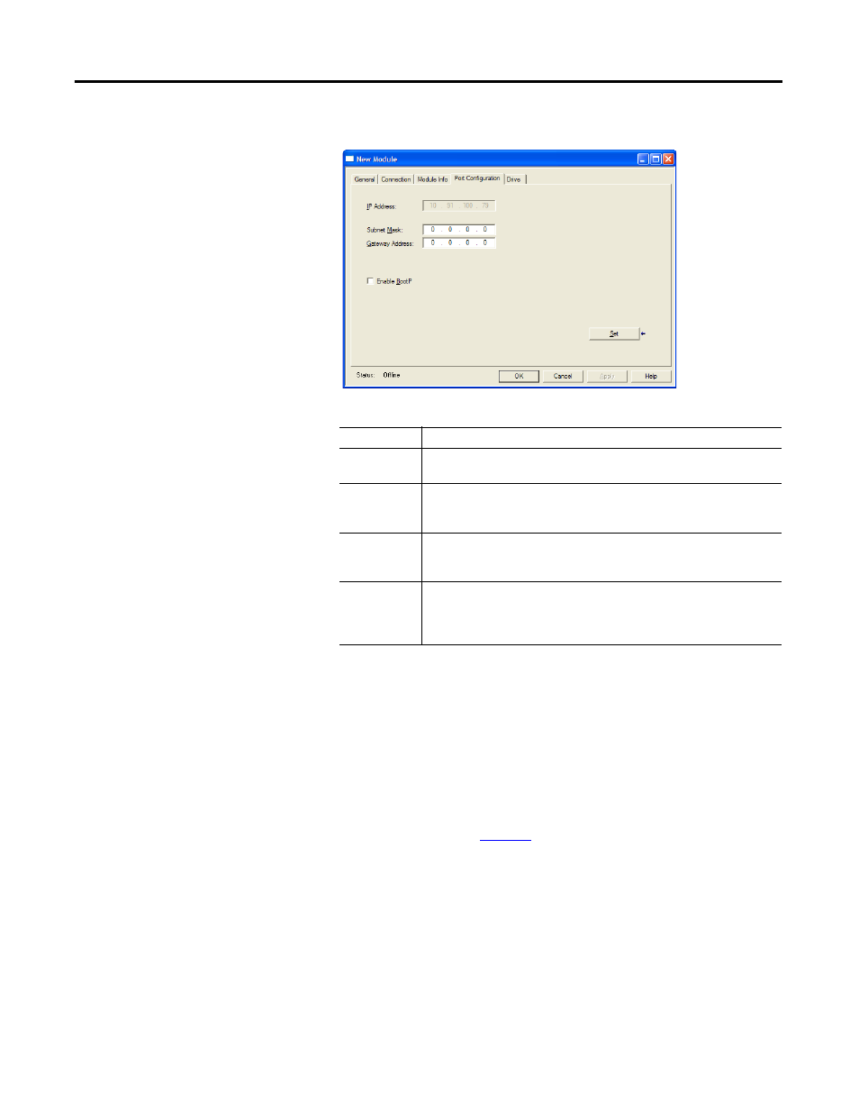
On the New Module screen, click the Port Configuration tab.
11.
In the Port Configuration tab screen, edit the following information.
12.
Click Set to save the Port Configuration information which sets the
corresponding offline Subnet Cfg x and Gateway Cfg x parameters in the
adapter.
13.
Click OK on the New Module screen.
The new node (‘My_PowerFlex_70_EC_Drive’ in this example) now
appears under the bridge (‘My_EtherNet_IP_Bridge’ in this example) in
the I/O Configuration folder. If you double-click the Controller Tags,
you will see that module-defined data types and tags have been
automatically created (
Figure 9
). Note that all tag names are defined and
Datalinks include the assigned drive parameter name. After you save
and download the configuration, these tags allow you to access the Input
and Output data of the drive via the controller’s ladder logic.
BoxSetting
IP Address
The IP address of the adapter that was already set in the General tab. This
field is not configurable (grayed out).
Subnet Mask
The Subnet Mask configuration setting of the network. This setting must
match the setting of other devices on the network (for example,
255.255.255.0).
Gateway
Address
The Gateway Address configuration setting of the network. This setting must
match the setting of other devices on the network (for example,
10.91.100.1).
Enable BootP
When this box is checked, BOOTP is enabled in the adapter and will ignore
the IP address set in the General tab. When unchecked, the controller uses
the set IP address. This is another method to enable/disable BOOTP in the
adapter. For this example, leave this box unchecked.