Applying power, Start-up status indications – Rockwell Automation 20-COMM-ER 20-COMM-ER Dual-Port EtherNet/IP Communication Adapter User Manual User Manual
Page 24
24
Rockwell Automation Publication 20COMM-UM015B-EN-P - July 2013
Chapter 2 Installing the Adapter
To connect to the second drive, attach another Ethernet cable between
the first drive’s option module ENET2 network port and the second
drive’s option module ENET1 network port.
To connect additional drives, repeat these daisy-chain connections in
the same way.
5.
Route the other end of the Ethernet cable through the bottom of the
PowerFlex drive (
) and insert its Ethernet cable plug into the mating
adapter receptacle.
Applying Power
Install the device cover or close the drive door, and apply power to the device. The
adapter receives its power from the connected device. When you apply power to
the adapter for the first time, its topmost PORT status indicator should be steady
green or flashing green after an initialization. If it is red, there is a problem. See
Start-Up Status Indications
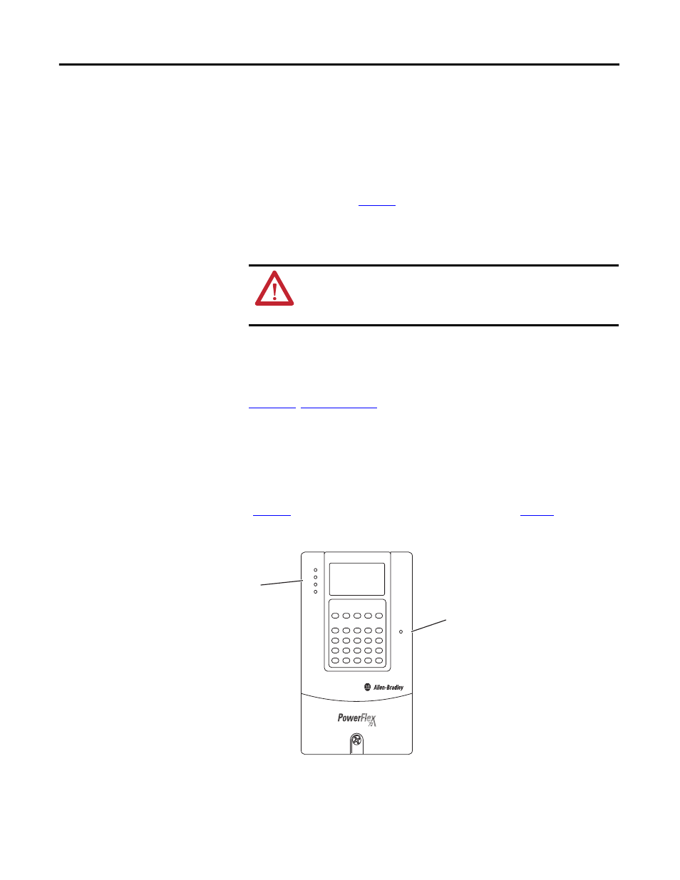
After power has been applied, the status indicators for the device and
communications adapter can be viewed on the front of the device
(
Figure 7
). Possible start-up status indications are shown in
Table 1
.
Figure 7 - Drive and Adapter Status Indicators (location will vary by device)
ATTENTION: Risk of equipment damage, injury, or death exists.
Unpredictable operation may occur if you fail to verify that parameter
settings are compatible with your application. Verify that settings are
compatible with your application before applying power to the drive.
➋
➊
PS
NS
STS
LS1
LS2