Connecting the adapter to the network – Rockwell Automation 20-COMM-ER 20-COMM-ER Dual-Port EtherNet/IP Communication Adapter User Manual User Manual
Page 23
Rockwell Automation Publication 20COMM-UM015B-EN-P - July 2013
23
Installing the Adapter Chapter 2
Connecting the Adapter to
the Network
1.
Remove power from the drive.
2.
Use static control precautions.
3.
Connect one end of an Ethernet cable to the network. See
for an
example of wiring to an EtherNet/IP network.
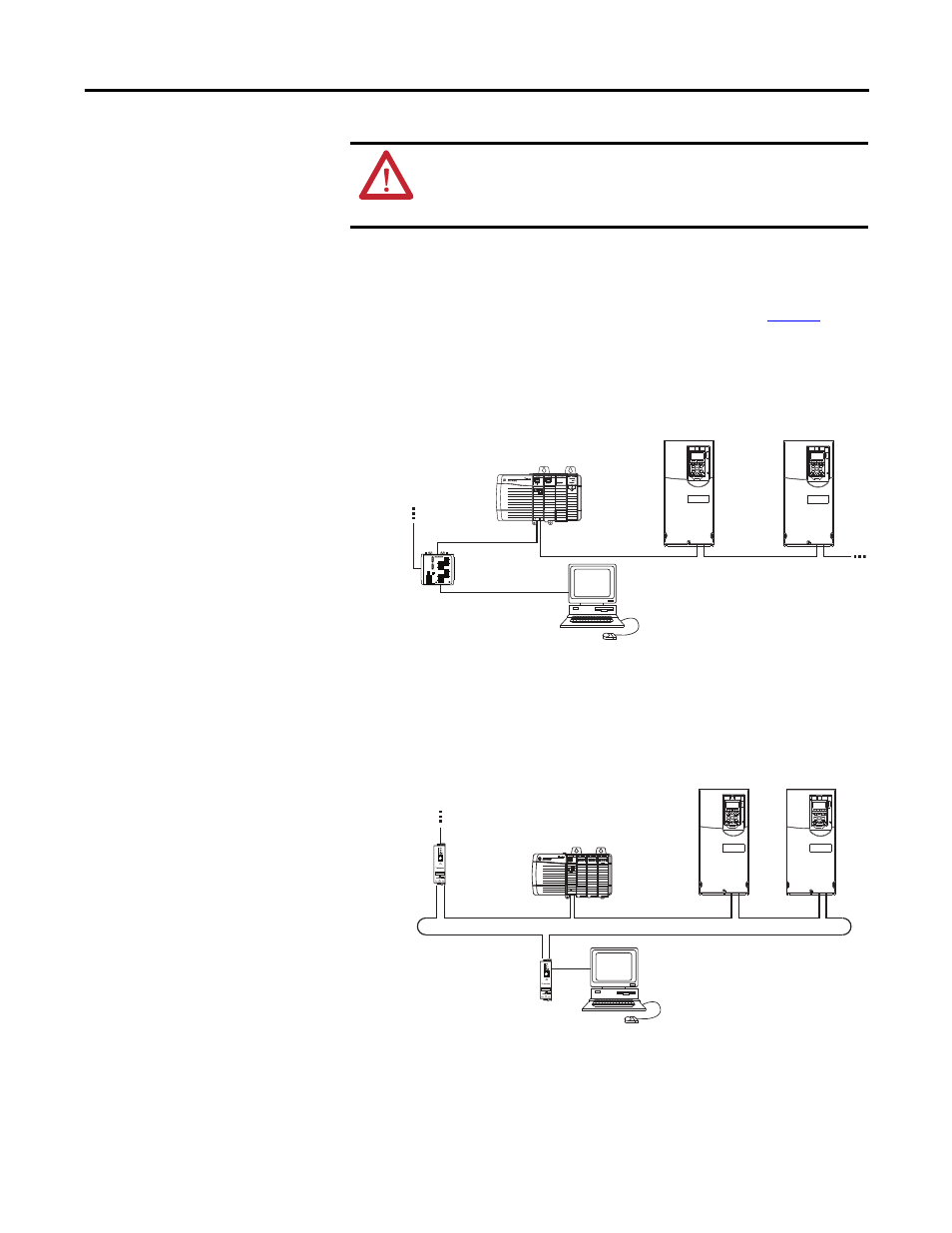
Figure 5 - Connecting the Ethernet Cable in a Linear Topology Network
Figure 6 - Connecting the Ethernet Cable in a DLR Topology Network
4.
For Linear or DLR Network Topology, route the other end of the Ethernet
cable from the network through the bottom of the first drive, and insert its
cable plug into the option module ENET1 network port.
ATTENTION: Risk of injury or death exists. The PowerFlex drive may
contain high voltages that can cause injury or death. Remove power from
the drive, and then verify power has been discharged before installing or
removing the adapter.
Controller
(ControlLogix controller
shown with 1756-EN2TR Bridge)
Drive or SMC
(1)
(with 20-COMM-ER Option Modules)
Ethernet
Switch
Computer with
Ethernet Connection
To other
EtherNet/IP
networks
(1)
The option module’s ENET1 and
ENET2 network ports are used.
Controller
(ControlLogix controller
shown with 1756-EN2TR Bridge)
Drive or SMC
(1)
(with 20-COMM-ER Option Modules)
Computer with
Ethernet Connection
To other
EtherNet/IP
networks
1783-ETAP
1783-ETAP
(1)
The option module’s ENET1 and
ENET2 network ports are used.