Selecting master-slave or peer-to-peer, Setting a master-slave hierarchy 36, Setting a master-slave hierarchy (scanner-to-drive – Rockwell Automation 20-COMM-ER 20-COMM-ER Dual-Port EtherNet/IP Communication Adapter User Manual User Manual
Page 36: Selecting master-slave or peer-to, Peer
36
Rockwell Automation Publication 20COMM-UM015B-EN-P - July 2013
Chapter 3 Configuring the Adapter
Selecting Master-Slave or
Peer-to-Peer
A hierarchy determines the type of device with which the adapter exchanges data.
In a Master-Slave hierarchy, the adapter exchanges data with a master, such as a
scanner or bridge (1756-ENBT, 1756-EN2T, 1747-L5-xxx, and so forth). In a
Peer-to-Peer hierarchy, the adapter exchanges data with one or more EtherNet/IP
adapters in other devices. (The devices must have compatible Logic Command/
Status words.)
For both Master-Slave and Peer-to-Peer hierarchies, the devices exchanging data
must be on the same IP subnet. See ‘IP Addresses’ in the for information about
IP subnets.
Setting a Master-Slave Hierarchy (Scanner-to-Drive
Communication)
1.
Enable the desired I/O in Parameter 25 - [DPI I/O Cfg].
Setting the I/O Configuration on page 35
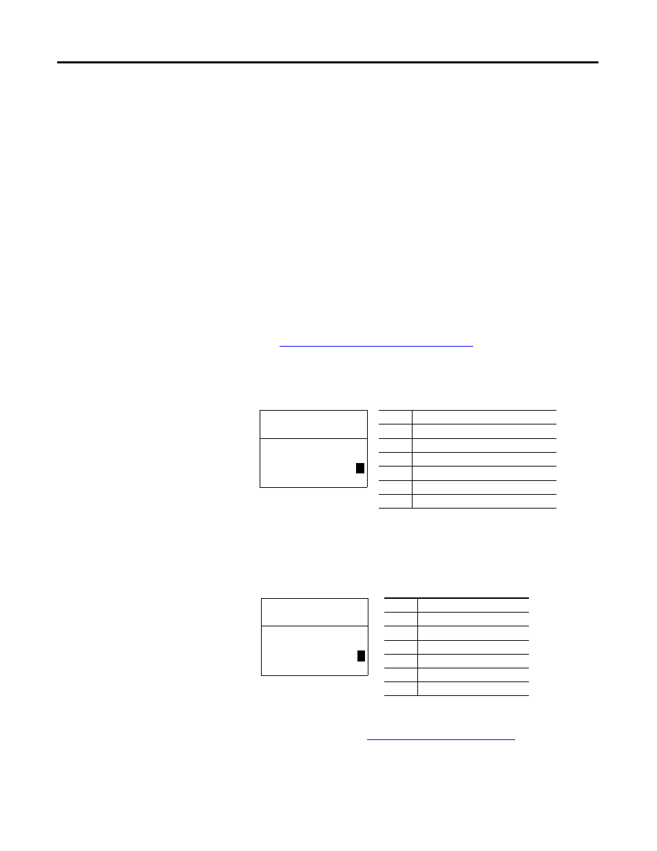
2.
Set the bits in Parameter 37 - [M-S Input].
This parameter determines the data received from the master by the
device. A ‘1’ enables the I/O and a ‘0’ disables the I/O.
Bit 0 is the right-most bit. It is highlighted above and equals ‘1’.
3.
Set the bits in Parameter 38 - [M-S Output].
This parameter determines the data transmitted from the device to the
scanner. A ‘1’ enables the I/O and a ‘0’ disables the I/O.
Bit 0 is the right-most bit. It is highlighted above and equals ‘1’.
4.
Resetting the Adapter on page 43
.
Bit
Description
0
Logic Command/Reference (Default)
1
Datalink A Input
2
Datalink B Input
3
Datalink C Input
4
Datalink D Input
5…15 Not Used
Port 5 Device
20-COMM-ER
Parameter #: 37
M-S Input
x x x x x x x x x x x 0 0 0 0
1
Cmd/Ref
b00
Bit
Description
0
Status/Feedback (Default)
1
Datalink A Output
2
Datalink B Output
3
Datalink C Output
4
Datalink D Output
5…15 Not Used
Port 5 Device
20-COMM-ER
Parameter #: 38
M-S Output
x x x x x x x x x x x 0 0 0 0
1
Status/Fdbk
b00