T072, T073, E if – Rockwell Automation 22C PowerFlex 400 AC Drive FRN 1.xx - 7.xx User Manual
Page 79: Terminal block group, Continued), T072 [analog in 1 loss, T073 [analog in 2 sel
Programming and Parameters
3-21
PowerFlex 400 Adjustable Frequency AC Drive FRN 1.xx - 7.xx User Manual
Publication 22C-UM001I-EN-P
Terminal Block Group
(continued)
T072 [Analog In 1 Loss]
Related Parameter(s):
,
Stop drive before changing this parameter.
Selects drive action when an input signal loss is detected. Signal loss is defined as an analog signal
less than 1V or 2mA. The signal loss event ends and normal operation resumes when the input signal
level is greater than or equal to 1.5V or 3mA. If using a 0-10V analog input, set
[Analog In 1 Lo]
to a minimum of 20% (i.e. 2 volts).
The drive will fault on an F29
when the analog signal is lost if this parameter is used
for the PID feedback, and this parameter and
[PID Ref Sel] are both set to an option other than
0 “Disabled”.
Options
0 “Disabled” (Default)
1 “Fault (F29)”
F29 Analog Input Loss
2 “Stop”
Uses P037 [Stop Mode]
3 “Zero Ref”
Drive runs at zero speed reference.
4 “Min Freq Ref”
Drive runs at minimum frequency.
5 “Max Freq Ref”
Drive runs at maximum frequency.
6 “Preset Freq0”
Drive runs at A143 [Preset Freq 0].
7 “Hold Last”
(with FRN 6.xx and
later)
Drive uses last frequency command from analog input prior to
signal loss, or last PID reference prior to signal loss when
used as a PID reference.
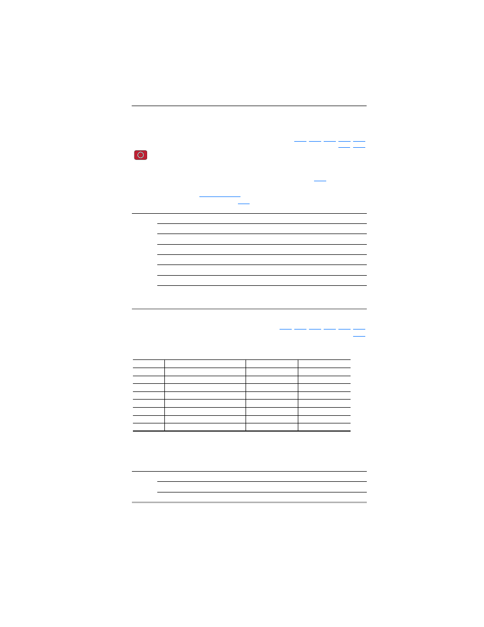
T073 [Analog In 2 Sel]
Related Parameter(s):
Sets the analog input signal mode (0-20mA, 4-20mA, 0-10V, -10 to +10V). This parameter must
match DIP Switch AI2 setting on the control board.
(1)
Setting 3 is only available on [Analog In 2 Sel]. Input 2 is isolated and supports a bi-polar input, so
that setting 3 determines if the voltage input is enabled for bipolar control. If bipolar is selected, P034
[Minimum Freq] and T074 [Analog In 2 Lo] are ignored. If input 2 is set up for current control, Bipolar
mode is not possible. If the analog input is inverted ([Analog In 2 Lo] > [Analog In 2 Hi]), Bipolar mode
is disabled and this input uses unipolar control only (negative values are treated like zero).
Values
Default:
2
Min/Max:
0/7
Display:
1
T073 Option
Setting
Input Range
DIP Switch AI2 Setting
0
Current Mode
0-20 mA
20 mA
1
Current Mode
4-20 mA
20 mA
2
Voltage Mode - Unipolar
0-10V
10V
3
(1)
Voltage Mode - Bipolar
-10 to +10V
10V
4
Current Mode (Square Root)
0-20 mA
20 mA
5
Current Mode (Square Root)
4-20 mA
20 mA
6
Voltage Mode - Unipolar (Square Root) 0-10V
10V
7
(1)
Voltage Mode - Bipolar (Square Root)
-10 to +10V
10V