22 installation/wiring – Rockwell Automation 22C PowerFlex 400 AC Drive FRN 1.xx - 7.xx User Manual
Page 34
1-22
Installation/Wiring
PowerFlex 400 Adjustable Frequency AC Drive FRN 1.xx - 7.xx User Manual
Publication 22C-UM001I-EN-P
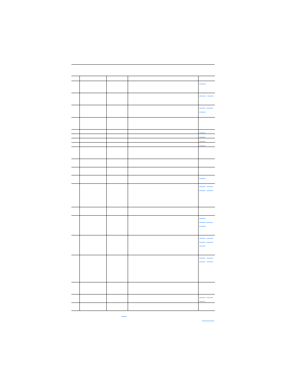
Table 1.H Control I/O Terminal Designations
No. Signal
Default
Description
Param.
01
Stop
(1)
/
Function Loss
Coast
Factory installed jumper or a normally closed input must
be present for the drive to start.
Program with P036 [Start Source].
02
Start/Run FWD
–
HAND Mode: Command comes from Integral Keypad.
AUTO Mode: I/O Terminal 02 is active.
Program with P036 [Start Source].
03
Direction/Run REV
Rev Disabled
To enable reverse operation, program with A166
[Reverse Disable].
Program with P036 [Start Source].
,
04
Digital Common
–
For digital inputs. Tied to I/O Terminal 09.
Electronically isolated with digital inputs from analog I/O
and opto output.
05
Digital Input 1
Purge
(2)
Program with T051 [Digital In1 Sel].
06
Digital Input 2
Local
Program with T052 [Digital In2 Sel].
07
Digital Input 3
Clear Fault
Program with T053 [Digital In3 Sel].
08
Digital Input 4
Comm Port
Program with T054 [Digital In4 Sel].
09
Digital Common
–
For digital inputs. Tied to I/O Terminal 04.
Electronically isolated with digital inputs from analog I/O
and opto output.
10
Opto Common
–
For opto-coupled outputs. Electronically isolated with
opto output from analog I/O and digital inputs.
11
+24V DC
–
Drive supplied power for digital inputs.
Referenced to Digital Common. Max. Output: 100mA.
12
+10V DC
–
Drive supplied power for 0-10V external potentiometer.
Referenced to Analog Common. Max. Output: 15mA.
13
Analog Input 1
0-10V
External 0-10V (unipolar), 0-20mA or 4-20mA input
supply or potentiometer wiper. Default input is 0-10V.
For current (mA) input, set AI1 DIP Switch to 20mA.
Program with T069 [Analog In 1 Sel].
Input Impedance:
100k ohm (Voltage Mode)
250 ohm (Current Mode)
14
Analog Common 1
–
Common for Analog Input 1 and Analog Output 1 and 2.
Electrically isolated from digital I/O and opto output.
15
Analog Output 1
OutFreq 0-10
Default analog output is 0-10V.
For current (mA) value, set AO1 DIP Switch to 20mA.
Program with T082 [Analog Out1 Sel].
Maximum Load:
4-20mA = 525 ohm (10.5V)
0-10V = 1k ohm (10mA)
16
Analog Output 2
OutCurr 0-10
Default analog output is 0-10V.
For a current (mA) value, set AO2 DIP Switch to 20mA.
Program with T085 [Analog Out2 Sel].
Maximum Load:
4-20mA = 525 ohm (10.5V)
0-10V = 1k ohm (10mA)
17
Analog Input 2
0-10V
Optically isolated external 0-10V (unipolar), ±10V
(bipolar), 0-20mA or 4-20mA input supply or
potentiometer wiper. Default input is 0-10V.
For current (mA) input, set AI2 DIP Switch to 20mA.
Program with T073 [Analog In 2 Sel].
Input Impedance: 100k ohm (Voltage Mode)
250 ohm (Current Mode)
18
Analog Common 2
–
For Analog Input 2. Electronically isolated from digital I/O
and opto output. With Analog Input 2, provides one fully
isolated analog input channel.
19
Opto Output
At Frequency
Program with T065 [Opto Out Sel].
20
RS485 (DSI) Shield –
Terminal connected to Safety Ground - PE when using
the RS485 (DSI) Communication Port.
(1)
See Footnotes (1) and (4) on page
(2)
Important information regarding Stop commands and the [Digital Inx Sel] Purge option is provided on