Reflected wave protection, Output disconnect, Power terminal block – Rockwell Automation 22C PowerFlex 400 AC Drive FRN 1.xx - 7.xx User Manual
Page 28
1-16
Installation/Wiring
PowerFlex 400 Adjustable Frequency AC Drive FRN 1.xx - 7.xx User Manual
Publication 22C-UM001I-EN-P
Reflected Wave Protection
The drive should be installed as close to the motor as possible.
Installations with long motor cables may require the addition of external
devices to limit voltage reflections at the motor (reflected wave
phenomena). See
for recommendations.
The reflected wave data applies to all frequencies 2 to 10 kHz.
For 240V ratings, reflected wave effects do not need to be considered.
Table 1.C Maximum Cable Length Recommendations
Output Disconnect
The drive is intended to be commanded by control input signals that will
start and stop the motor. A device that routinely disconnects then
reapplies output power to the motor for the purpose of starting and
stopping the motor should not be used. If it is necessary to disconnect
power to the motor with the drive outputting power, an auxiliary contact
should be used to simultaneously disable drive control run commands.
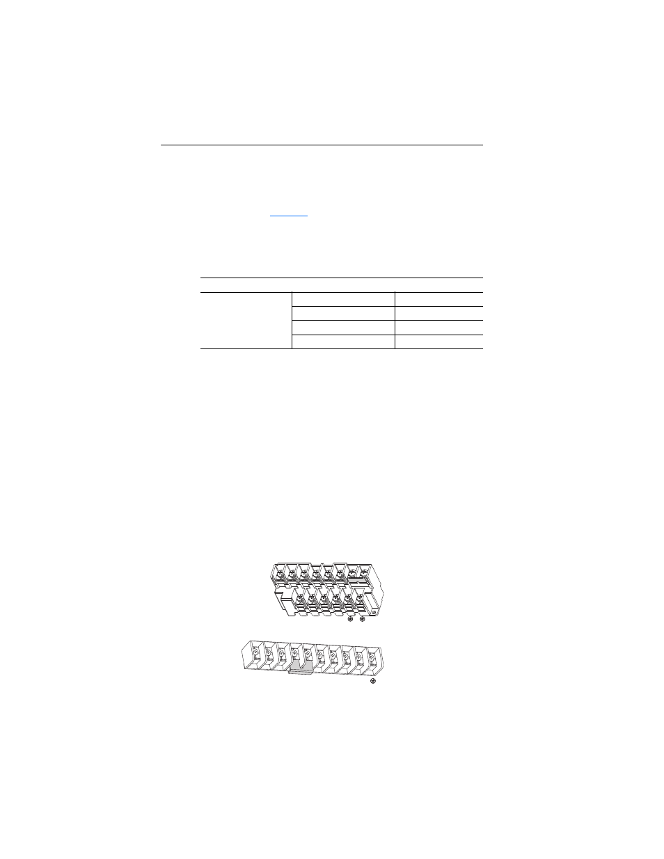
Power Terminal Block
Frame C, D, F, G and H drives utilize a finger guard over the power
wiring terminals. Replace the finger guard when wiring is complete.
Figure 1.8 Power Terminal Blocks (Frames C through D)
Reflected Wave
380-480V Ratings
Motor Insulation Rating
Motor Cable Only
(1)
(1)
Longer cable lengths can be achieved by installing devices on the output of the drive.
Consult factory for recommendations.
1000 Vp-p
7.6 meters (25 feet)
1200 Vp-p
22.9 meters (75 feet)
1600 Vp-p
152.4 meters (500 feet)
Frame D
R/L1 S/L2 T/L3
P1
P2
DC– U/T1 V/T2 W/T3
Frame C
R/L1 S/L2 T/L3 U/T1 V/T2 W/T3 P2
P1
BR–
BR+
DC+
DC–