Appendix e, Modbus rtu protocol, Network wiring – Rockwell Automation 22C PowerFlex 400 AC Drive FRN 1.xx - 7.xx User Manual
Page 191: Emodbus rtu protocol, Appendix
PowerFlex 400 Adjustable Frequency AC Drive FRN 1.xx - 7.xx User Manual
Publication 22C-UM001I-EN-P
Appendix
E
Modbus RTU Protocol
PowerFlex 400 drives support the RS485 (DSI) protocol to allow
efficient operation with Rockwell Automation peripherals. In addition,
some Modbus functions are supported to allow simple networking.
PowerFlex 400 drives can be multi-dropped on an RS485 network using
Modbus protocol in RTU mode.
For information regarding DeviceNet or other communication protocols,
refer to the appropriate user manual.
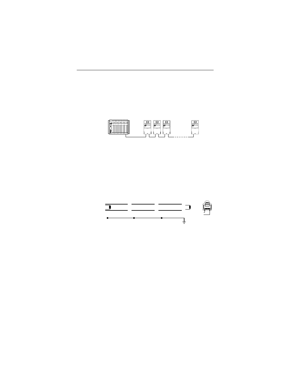
Network Wiring
Network wiring consists of a shielded 2-conductor cable that is
daisy-chained from node to node.
Figure E.1 Network Wiring Diagram
Only pins 4 and 5 on the RJ45 plug should be wired. The other pins on
the PowerFlex 400 RJ45 socket contain power, etc. for other Rockwell
Automation peripheral devices and must not be connected.
Wiring terminations on the master controller will vary depending on the
master controller used and “TxRxD+” and “TxRxD-” are shown for
illustration purposes only. Refer to the master controller’s user manual
for network terminations. Note that there is no standard for the “+” and
“-” wires, and consequently Modbus device manufacturers interpret
them differently. If you have problems with initially establishing
communications, try swapping the two network wires at the master
controller.
Controller
Master
PowerFlex 400
Node 1
4
5
PowerFlex 400
Node 2
4
5
PowerFlex 400
Node "n"
4
5
TxRxD+
TxRxD-
TxRxD+
TxRxD-
TxRxD+
TxRxD-
NOTE: The shield should be grounded at ONLY ONE location.
Shield
Shield
Shield
120 ohm resistor
120 ohm resistor
FRONT
PIN 8
PIN 1